Posted on Leave a comment

Global Variable Frequency Drive (VFD) repair center

“Longi Electromechanical” has more than 20 years of experience in industrial control maintenance, and is one of the earliest companies engaged in VFD repair. Equipped with artificial intelligence AI maintenance instruments, it specializes in emergency repair of various equipment, with high technical efficiency. It has repaired more than 200,000 units of equipment, including ultrasonic, robot, charging pile, inverter,Variable Frequency Drive (VFD), touch screen, servo, intelligent instrument, industrial control machine, PLC and other products. General problems can be repaired on the same day. LONGI promises you that “if it can’t be repaired, we won’t charge you”. And it provides lifelong maintenance service and free technical consultation for inspection! For urgent repair consultation, please call the contact number or add WHATSAPP maintenance hotline: +8618028667265 Mr. Guo

From European and American brands to Japanese, Korean, and Taiwanese ones, until various domestic brands, we have repaired countless models and specifications of VFDs. In the process of serving our customers, we have continuously learned and accumulated maintenance experience to enhance our skills. We specialize not only in repairing VFDs but also in summarizing various maintenance experiences, elevating them to a theoretical level. We have published the book “VFD Maintenance Technology” and offered VFD maintenance training, thereby promoting the development of the VFD maintenance industry. Longi Electromechanical Company has repaired VFDs from the following brands:

European and American Brands

ABB drives, SEW drives, LUST VFD, LENZE VSD, Schneider drives, CT drives, KEB VSD, Siemens drives, Eurotherm VFD, G.E. VFD, VACON VSD, Danfoss VFD, SIEI VFD, AB VFD, Emerson VFD, ROBICON VFD, Ansaldo VFD, Bosch Rexroth VSD, etc.

Japanese Brands:

Fuji INVERTER, Mitsubishi INVERTER, Yaskawa INVERTER, Omron INVERTER, Panasonic INVERTER, Toshiba INVERTER, Sumner INVERTER, Tooka INVERTER, Higashikawa INVERTER, Sanken INVERTER, Kasia INVERTER, Toyo INVERTER, Hitachi INVERTER, Meidensha INVERTER, etc.

Taiwanese Brands:

Oulin INVERTER, Delta INVERTER, Taian INVERTER, Teco INVERTER, Powtran INVERTER, Dongling INVERTER, Lijia INVERTER, Ningmao INVERTER, Sanji INVERTER, Hongquan INVERTER, Dongli INVERTER, Kaichi INVERTER, Shenghua INVERTER, Adlee INVERTER, Shihlin INVERTER, Teco INVERTER, Sanchuan INVERTER, Dongweiting INVERTER, Fuhua INVERTER, Taian INVERTER (note: Taian is repeated, possibly a mistake in the original list), Longxing INVERTER, Jiudesongyi INVERTER, Tend INVERTER, Chuangjie INVERTER, etc.

Chinese Mainland brands:

Senlan Inverter, Jialing Inverter, Yineng Inverter, Hailipu Inverter, Haili Inverter, Lebang Inverter, Xinnuo Inverter, Kemron Inverter, Alpha Inverter, Rifeng Inverter, Shidai Inverter, Bost Inverter, Gaobang Inverter, Kaituo Inverter, Sinus Inverter, Sepaxin Inverter, Huifeng Inverter, Saipu Inverter, Weier Inverter, Huawei Inverter, Ansheng Inverter, Anbangxin Inverter, Jiaxin Inverter, Ripu Inverter, Chint Inverter, Delixi Inverter, Sifang Inverter, Geli Te Inverter, Kangwo Inverter, Jina Inverter, Richuan Inverter, Weikeda Inverter, Oura Inverter, Sanjing Inverter, Jintian Inverter, Xilin Inverter, Delixi Inverter, Yingweiteng Inverter, Chunri Inverter, Xinjie, Kemron-Bong Inverter, Nihonye Inverter, Edison Inverter

Other brands:
Migao VFD, Rongqi VFD, Kaiqi VFD, Shiyunjie VFD, Huichuan VFD, Yuzhang VFD, Tianchong VFD, Rongshang Tongda VFD, LG VFD, Hyundai VFD, Daewoo VFD, Samsung VFD, etc.

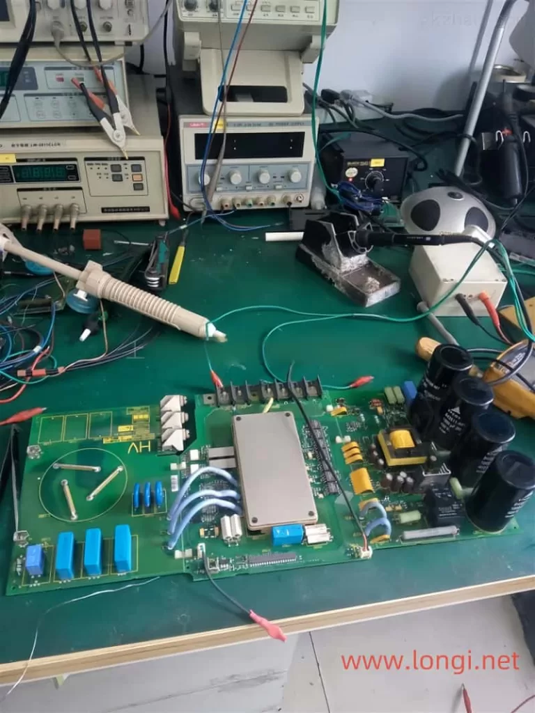
Longi Electromechanical Company specializes in the maintenance of VFDs and strictly requires its engineers to followlow standard operating procedures. Upon receiving a unit, the engineers carefully inspect its exterior and clarify any fault conditions with the customer before beginning work. Any removed circuit boards are cleaned using ultrasonic cleaning equipment. Repaired circuit boards are coated with high-temperature and high-pressure-resistant insulating paint, dried in a drying machine, and then reinstalled in the VFD, with measures taken to prevent corrosion and interference.
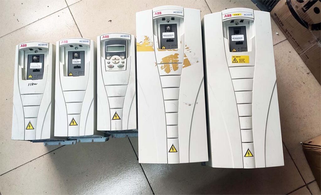
The repaired VFD will undergo a simulated operation with load using a heavy-load test bench to avoid any potential issues that may arise under actual load conditions on site.

When it comes to VFD maintenance, most cases are related to the equipment on site. Sometimes a standalone unit may have been repaired, but it doesn’t work properly when installed on site. In some cases, the problem lies with the system rather than the VFD itself. For such issues, if the customer requests on-site service, we will do our utmost to resolve the problem for them. If the location is far away, such as in another province, we can use tools like video conferencing and phone calls to allow our engineers to remotely diagnose and resolve the on-site issues for the customer.

Posted on Leave a comment

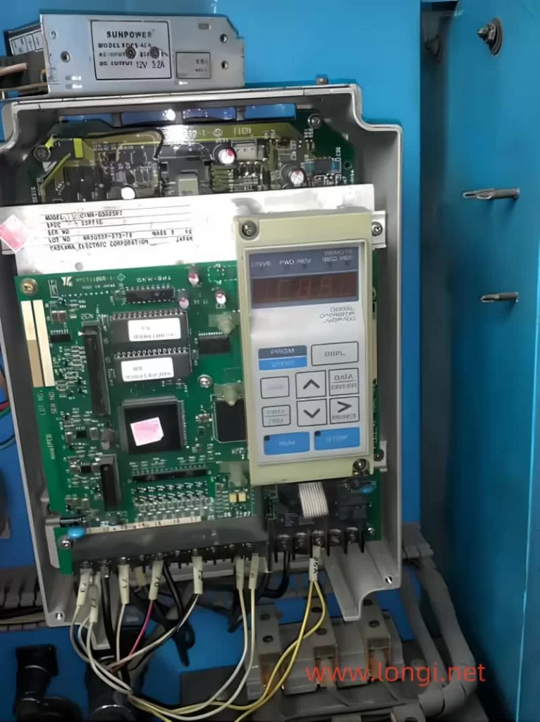
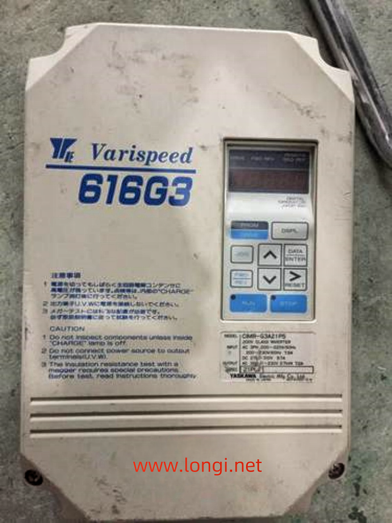
Repairing the Stubborn GF Fault in Yaskawa 616G3 55kW Frequency Converter

Repairing a frequency converter, especially one that reports a stubborn ground fault (GF), can be a challenging and frustrating task. Recently, I encountered such an issue with a Yaskawa 616G3 55kW frequency converter. Despite the common advice to replace the board, I delved deeper into the problem, determined to find a logical solution. This article outlines the step-by-step process I followed to diagnose and repair the GF fault without replacing any major components.

Initial Diagnosis and Background

The Yaskawa 616G3 frequency converter had been out of service for two to three years before it arrived at our repair department. Upon inspection, we found that two of the three-phase power input rectifier modules and two of the six inverter IGBT modules were damaged. The driver board had also suffered some component damage due to the module failure.

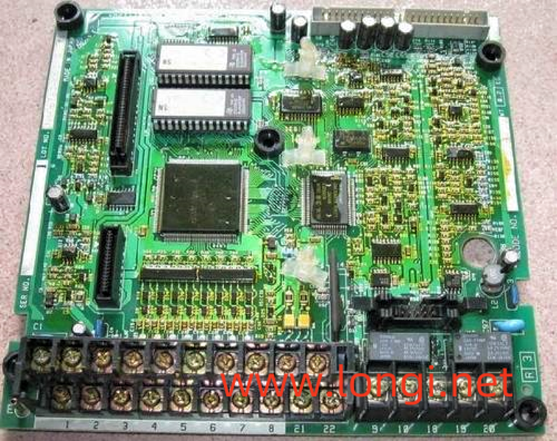
The GF fault typically indicates an issue with the drive circuit or the IGBT module itself, especially during the initial startup stage when the three-phase output voltage has not yet been established. Understanding the structure of the protection circuit helped narrow down the potential causes. The GF and OC (load-side short circuit) fault signals are fed directly to the CPU by the protection circuit of the driving circuit board.

Driver and Protection Circuits Inspection

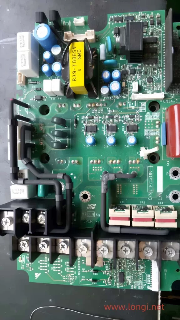
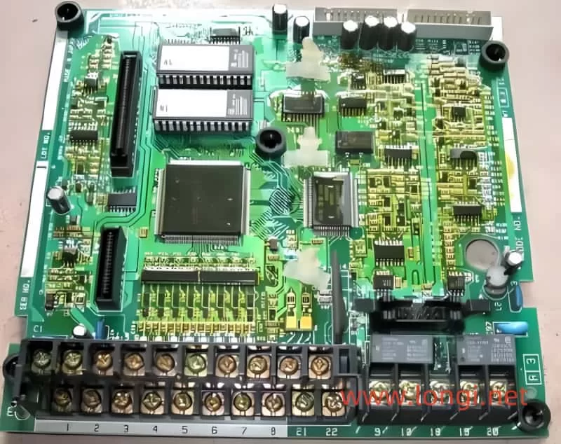
The driver circuit of the Yaskawa frequency converter includes six pulse signals from the CPU, isolated and amplified by six TLP250 ICs, and sent to the IGBT modules. Additionally, six TLP750 ICs form a module fault protection circuit, reporting GF and OC signals to the CPU. There are also three 2501 optocouplers responsible for detecting fuse status.

After disconnecting the driver board and CPU motherboard, I replaced the damaged components in the power amplifier circuit. The switch power supply and motherboard appeared to be functioning correctly. I manually cleared other potential faults, such as overvoltage, undervoltage, overheating, and fan issues, to ensure the drive circuit could output normal excitation pulses.

Addressing the FU Fault

During the initial tests, the circuit reported an FU (fuse) fault. After inspecting the relevant optocoupler components and circuit components, I found that the copper foil strip of the N lead was broken due to mold. This caused the fuse detection circuit to assume the fuse was broken. I repaired the moldy copper foil strip and retested the circuit, which resolved the FU fault.

Further Investigation and Component Replacement

With the FU fault resolved, I pressed the RUN button on the operation panel and measured the six pulses output by the drive circuit, all of which were normal. However, the GF fault persisted. I re-inspected the driver board, measuring all circuit components and short-circuiting the GF fault feedback optocoupler, but the GF fault still tripped.

Further investigation revealed a poor contact between a diode in the IGBT voltage drop detection circuit and the copper foil strip. I also found that the positive voltage of the W-phase transistor driver pulse was low, indicating an issue with the driver IC. After replacing the faulty A3320 IC, the output pulse amplitude returned to normal.

The Stubborn GF Fault

Despite repairing the identified issues, the GF fault still occurred during startup. I used the fault zone cutting method to narrow down the fault range, eventually finding that the IGBT driver circuit (protection circuit) of the U-arm was prone to reporting the GF fault. A diode with a poor contact was identified and replaced.

However, even after these repairs, the GF fault persisted. I then conducted a series of tests, including short-circuiting the module detection circuit’s transistors to relieve the fault protection function. During these tests, I observed an abnormal phenomenon: the series-connected light bulb lit up with high brightness after the start signal was activated, indicating a potential issue with the IGBT modules or driving circuit.

Discovering the Common Cause

After ruling out issues with the driving circuit and modules, I focused on the common factors that could affect all six protection circuits. I noticed that the leads of the capacitor bank, which were longer due to the repair setup, could be introducing inductance into the circuit. This inductance could generate induced electromotive force and current, interfering with the module fault detection circuit.

To test this hypothesis, I formally installed the machine, limiting the lead inductance of the capacitor bank within the allowable value. After the installation, the Yaskawa frequency converter operated normally without tripping the stubborn GF fault.

Conclusion

Repairing the GF fault in the Yaskawa 616G3 55kW frequency converter was a challenging but rewarding experience. By thoroughly understanding the protection circuit and methodically diagnosing each potential issue, I was able to repair the machine without replacing any major components. The key to solving the stubborn GF fault was identifying the common cause—inductance in the capacitor bank leads—and addressing it through proper installation.

This case study highlights the importance of logical reasoning and thorough investigation in repairing electronic equipment. It also demonstrates that, with patience and persistence, even stubborn faults can be resolved without resorting to costly board replacements.

Posted on Leave a comment

Different scenarios of “GF” ground fault are reflected in the maintenance of Yaskawa 616G3 VSD drive

The power on display is normal. Start the operation, that is, jump “GF” fault, but it does not run or shows no signs of running. I quickly jumped over the ground fault. The “GF” fault at this time is equivalent to the “OC” fault of other frequency converters, and the fault is located in the inverter module or driving circuit. At the moment when the CPU sends the trigger pulse, it detects an abnormally large pressure drop in a certain IGBT tube and fails to open it normally during the arrival of the trigger pulse. In fact, during this time, the current transformer of the frequency converter did not detect the output current signal at all. At this point, the “GF” fault signal is fed back to the CPU by the module fault detection circuit of the driving circuit. (This fault action was determined by testing.)

Repair and inspection: Check the quality of the inverter block, especially the inspection of the trigger terminal cannot be ignored; Check the driving circuit, especially the filter capacitor of the driving power supply, and measure whether the driving voltage is normal, but whether there is a certain current driving ability.

  1. Jumping “GF” fault during operation is a fault reported by the current detection circuit. There are two aspects that need to be distinguished. On the one hand, it is a normal fault shutdown action, where the current transformer detects abnormal overcurrent and reports to the CPU to implement fault shutdown protection; On the one hand, the subsequent current signal processing circuit of the current transformer is faulty, such as the variable value of the resistor element, which causes the “GF” fault voltage setting point to drift, resulting in false alarm faults. The signal from the current transformer is processed through an operational amplifier, sent to the CPU for current display and fault alarm processing, and sent to a voltage comparator, reporting a “GF” fault. (Note: The subsequent circuit of this current transformer was not thoroughly investigated, but it was inferred from numerous fault phenomena and is for reference only.)
    Repair and inspection: When it is confirmed to be a false alarm fault, it is not necessarily necessary to replace the motherboard for repair. Detailed inspection of the current transformer and its subsequent circuits should be able to repair it.
  2. By the way, when an overcurrent fault is reported during operation for OL1, OL2, and OL3, it is detected by the current transformer and subsequent current signal processing circuit during operation. After sending the current signal to the CPU, it is judged, frequency reduced, and processed to report the overcurrent fault signal. For sudden abnormal overcurrent faults, module damage, or abnormal driving circuit faults, the driving circuit will directly feedback to the CPU, and the CPU will report an OC fault.

This suggests different treatments for undervoltage and overvoltage faults in other frequency converters. For undervoltage, after power on, it is detected and delayed for at least 5 seconds before reporting. Started 5 seconds ago and was able to run, but then experienced an undervoltage fault; For overvoltage faults, the fault will trip immediately after power on and operation is prohibited. It can be seen that designers attach greater importance to overvoltage faults than undervoltage faults. It can also be known that overvoltage faults pose greater harm to frequency converters than undervoltage faults do to frequency converters. And the handling of different fault alarms by designers can also be understood.