I. Introduction to Operation Panel Functions
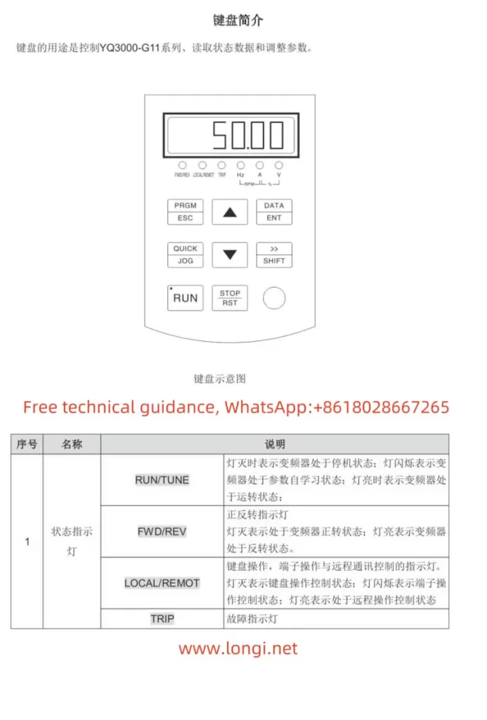
The Yuqiang Inverter YQ3000-G11 series operation panel integrates multiple functions, facilitating parameter setting and status monitoring for users. The panel mainly includes the following parts:

- Status Indicators: Including RUN/TUNE (running status), FWD/REV (forward/reverse indication), LOCAL/REMOT (local/remote operation indication), and TRIP (fault indication). These indicators visually display the current status of the inverter.
- Unit Indicators: Used to indicate the currently displayed unit, such as Hz (frequency), RPM (rotational speed), A (current), etc.
- Digital Display Area: A 5-digit LED display area used to display set frequency, output frequency, alarm codes, and other information.
- Analog Potentiometer: Equivalent to Al1, used to adjust the frequency.
- Button Area: Including PRG/ESC (program/exit), DATA/ENT (confirm), UP (increment), DOWN (decrement), SHIFT (right shift), RUN (run), STOP/RST (stop/reset), and QUICK/JOG (quick multifunction) buttons for parameter setting and function operation.
Setting and Eliminating Passwords
- Setting a Password:
- Enter the function code editing state, locate the P07.00 parameter, and set a non-zero value as the user password.
- After exiting the function code editing state, the password protection will take effect.
- Eliminating a Password:
- Re-enter the function code editing state and set the P07.00 parameter to 0.
- After exiting the function code editing state, the password protection will be canceled.
Restoring Default Parameters
- Enter the function code editing state, locate the P00.18 parameter, and set it to 1.
- The inverter will automatically restore the default parameter settings and clear the user password.

II. Terminal Start/Stop Mode and External Potentiometer Speed Adjustment Mode Settings
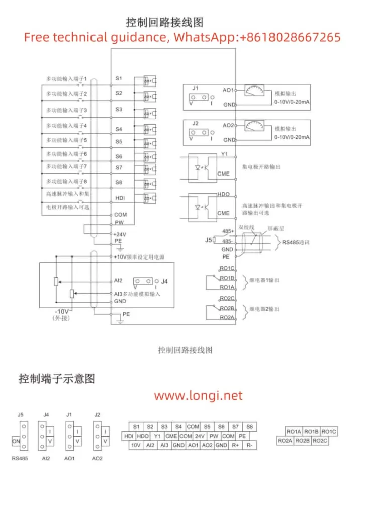
Wiring Instructions
- Terminal Start/Stop Mode:
- Connect external control signals to the multifunction input terminals of the inverter, such as FWD (forward), REV (reverse), and RUN/STOP terminals.
- Specific wiring should be done according to control requirements, referring to the wiring diagram.
- External Potentiometer Speed Adjustment Mode:
- Connect the output signal of the external potentiometer to the analog input terminals of the inverter, such as Al1 or Al2.
- Adjust the output range of the potentiometer to match the input requirements of the inverter.
Parameter Settings
- Terminal Start/Stop Mode:
- Set the P00.01 parameter to 1 to select the terminal operation command channel.
- Set the functions of S1~S8 multifunction terminals as needed, such as setting S1 as forward operation (FWD) and S2 as reverse operation (REV).
- External Potentiometer Speed Adjustment Mode:
- Set the P00.06 or P00.07 parameter to the corresponding analog input channel, such as selecting Al1 as the frequency setting source.
- Adjust the analog input parameters of the inverter according to the output range of the external potentiometer, such as the lower limit (P05.32) and upper limit (P05.34) of Al1.
III. Alarm Codes and Handling Methods
The Yuqiang Inverter YQ3000-G11 series provides abundant alarm codes to help users quickly locate fault causes. The following are some common alarm codes, their meanings, and handling methods:
- OC1 (Acceleration Overcurrent): Overcurrent occurs during the acceleration of the inverter.
- Handling Method: Check if the motor load is too large or appropriately extend the acceleration time.
- OC2 (Deceleration Overcurrent): Overcurrent occurs during the deceleration of the inverter.
- Handling Method: Check if the motor load is too large or appropriately extend the deceleration time.
- OV1 (Acceleration Overvoltage): Overvoltage occurs during the acceleration of the inverter.
- Handling Method: Check if the power supply voltage is too high or appropriately extend the acceleration time.
- UV (DC Bus Undervoltage Fault): The DC bus voltage of the inverter is lower than the undervoltage protection setting value.
- Handling Method: Check if the power supply voltage is normal or if the power supply lines are poorly connected.
- OL1 (Motor Overload): The operating current of the motor exceeds the overload protection setting value.
- Handling Method: Check if the motor load is too large or appropriately adjust the overload protection setting value.
- OL2 (Inverter Overload): The output current of the inverter exceeds the overload protection setting value.
- Handling Method: Check if the load is too large or if the inverter cooling is adequate.
- tE (Motor Self-learning Fault): A fault occurs during the motor self-learning process.
- Handling Method: Check if the motor connection is correct or re-perform motor self-learning.
- PIDE (PID Feedback Disconnection Fault): The PID feedback signal is lost.
- Handling Method: Check if the PID feedback line is properly connected or if the feedback sensor is normal.
When the inverter malfunctions, users should quickly locate the fault cause based on the alarm code and troubleshoot and repair it according to the corresponding handling method. At the same time, users should regularly maintain and inspect the inverter to ensure its normal operation.
Through this guide, we hope users can better understand and use the user manual for the Yuqiang Inverter YQ3000-G11 series, achieving efficient and safe inverter operation and maintenance.
