
The TECO T310 series inverter is a powerful and reliable variable frequency drive widely used in industrial automation, machinery, and pumping systems. To help users better operate and maintain this inverter, this article provides a detailed guide on the T310 series inverter’s operation panel functions, parameter settings, external control wiring, and troubleshooting.
I. Introduction to the Operation Panel Functions
1. Overview of Operation Panel Functions
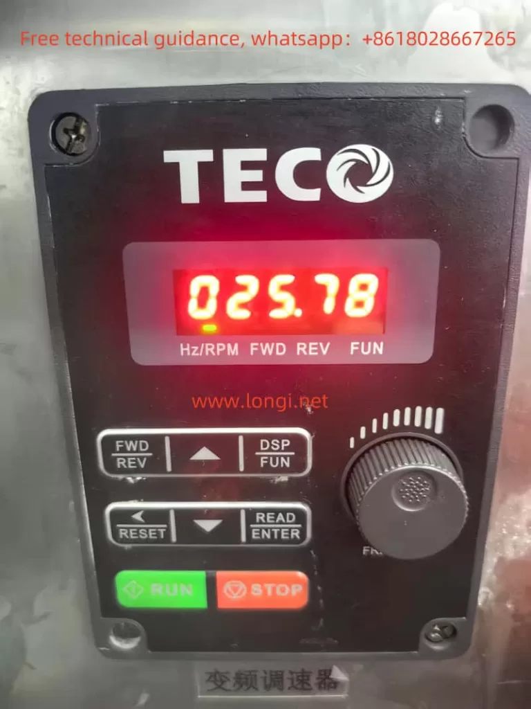
The T310 series inverter’s operation panel integrates display, control, and parameter setting functions. Users can perform operations such as starting, stopping, parameter setting, and fault diagnosis through the buttons and display screen on the panel. The main buttons on the panel include:
- RUN/STOP: Start or stop the inverter.
- ↑/↓: Adjust frequency or parameter values.
- FWD/REV: Switch the motor’s forward and reverse directions.
- DSP/FUN: Switch display modes (frequency display or parameter setting).
- : Reset or confirm parameter settings.
- READ/ENTER: Read or write parameter values.
2. How to Copy Parameters to Another Inverter
The T310 series inverter supports parameter copying, allowing users to export parameters from one inverter and import them into another. The specific steps are as follows:
- Export Parameters:
- Enter the parameter setting mode and select group 13 (Maintenance Function Group).
- Locate parameter 13-01 (Parameter Export), and press the READ/ENTER key.
- The display will show “COPY,” indicating that the parameters have been exported.
- Import Parameters:
- On the target inverter, enter the parameter setting mode and select group 13.
- Locate parameter 13-02 (Parameter Import), and press the READ/ENTER key.
- The display will show “PASTE,” indicating that the parameters have been imported.
3. How to Restore Parameters to Initial Settings
If you need to restore the inverter to its factory settings, follow these steps:
- Enter the parameter setting mode and select group 13.
- Locate parameter 13-08 (Initialization Setting), and press the READ/ENTER key.
- The display will prompt “RESET.” Press the READ/ENTER key to confirm, and the inverter will revert to its factory settings.
4. How to Set and Remove Passwords
The T310 series inverter supports password protection to restrict access to parameter settings. The steps to set a password are as follows:
- Enter the parameter setting mode and select group 00 (Basic Function Group).
- Locate parameter 00-31 (Password Setting), and press the READ/ENTER key.
- Enter a 4-digit password (range: 0000~9999), and press the READ/ENTER key to save.
- After setting the password, you will need to enter it to modify parameters in the parameter setting mode.
Remove Password:
- Enter the parameter setting mode and select group 00.
- Locate parameter 00-31, and press the READ/ENTER key.
- Set the password to 0000, and press the READ/ENTER key to save.
5. How to Set Parameter Access Restrictions
To prevent unauthorized parameter modifications, you can set parameter 00-30 (Parameter Lock) to restrict access:
- Enter the parameter setting mode and select group 00.
- Locate parameter 00-30, and press the READ/ENTER key.
- Set the parameter value to 1 (Locked State), and press the READ/ENTER key to save.
- Once locked, all parameters will be non-modifiable unless unlocked (set the parameter value to 0).
II. External Control Wiring and Parameter Settings
1. External Terminal Forward and Reverse Control
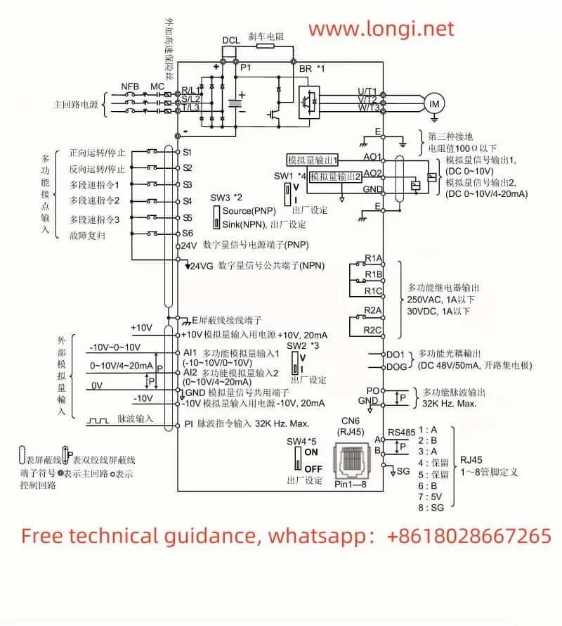
The T310 series inverter supports forward and reverse control of the motor through external terminals. The specific wiring and parameter settings are as follows:
- Terminal Wiring:
- S1: Forward input (default).
- S2: Reverse input (default).
- Parameter Settings:
- Enter the parameter setting mode and select group 03 (External Digital Input/Output Function Group).
- Locate parameters 03-00 (S1 Function Setting) and 03-01 (S2 Function Setting), and set them to forward and reverse control.
2. External Potentiometer Speed Control
You can control the inverter’s speed using an external potentiometer. The specific wiring and parameter settings are as follows:
- Terminal Wiring:
- AI1: Analog input terminal (0~10V or 4~20mA).
- Parameter Settings:
- Enter the parameter setting mode and select group 04 (External Analog Input/Output Function Group).
- Locate parameter 04-00 (AI1 Function Setting), and set it to frequency command.
- Set parameter 04-01 (AI1 Range) to 0~10V or 4~20mA, depending on the potentiometer’s output type.
III. Fault Codes and Troubleshooting
The T310 series inverter may encounter various faults during operation, and the inverter will display fault codes on the screen. Below are common fault codes, their meanings, and troubleshooting methods:
1. Common Fault Codes and Meanings
| Fault Code | Meaning | Possible Causes |
|---|---|---|
| OV | Overvoltage | Input voltage is too high or unstable. |
| UV | Undervoltage | Input voltage is too low or unstable. |
| OP | Overload | Motor load exceeds the inverter’s rated load. |
| OH | Overheating | Inverter internal temperature is too high. |
| GF | Ground Fault | Inverter grounding is poor or ground wire is disconnected. |
| OF | Output Fault | Output terminal short circuit or motor wiring fault. |
| CF | Communication Fault | Communication interface connection is abnormal or communication parameters are incorrect. |
2. Troubleshooting Methods
- OV/UV: Check if the input voltage is within the inverter’s rated range and ensure the power supply is stable.
- OP: Reduce the motor load or check for mechanical faults in the motor.
- OH: Check the inverter’s cooling conditions, ensure good ventilation, and clean the heat sink if necessary.
- GF: Check if the ground wire is securely connected and ensure proper grounding.
- OF: Check the output terminals and motor wiring for short circuits or open circuits.
- CF: Check the communication wiring and ensure the communication parameters are set correctly.
IV. Conclusion
The TECO T310 series inverter is a powerful and user-friendly variable frequency drive. By properly using the operation panel, setting parameters, and wiring external controls, users can achieve precise control of the motor. Understanding the inverter’s fault codes and troubleshooting methods can help users quickly resolve issues, improving system stability and reliability. This guide aims to provide valuable insights for users to better operate and maintain the T310 series inverter.