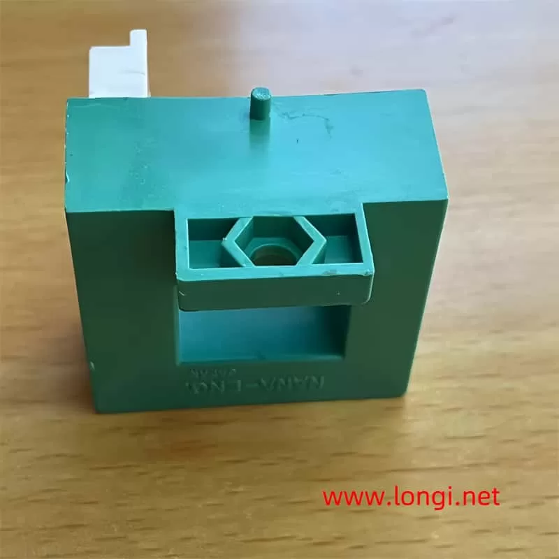
In the realm of frequency inverter circuits, transformers have evolved significantly. While early models relied on traditional transformers wound with through-core inductor coils, modern, mature circuits predominantly feature integrated, sealed current transformers constructed using Hall elements and pre-current detection circuits. These are often referred to as electronic current transformers and are categorized as either standard or non-standard types.

Standard electronic current transformers are readily available molded products in the market. For instance, a 10A/1V current transformer outputs a 1V signal for every 10A of current flowing through the circuit. On the other hand, non-standard types are custom-designed by frequency converter manufacturers and are not interchangeable. In case of damage, replacing them with the same model from the original manufacturer is usually necessary. However, with in-depth maintenance knowledge, different models can sometimes be used as temporary solutions until a permanent replacement is sourced.
The construction of electronic current transformers often involves the use of sealants, making them difficult to repair once damaged. This has led to much curiosity about their internal circuitry and repairability. During my experience repairing a Fuji frequency inverter, I needed to adjust the A/V ratio of the electronic current transformer, which required accessing its internal circuit. This prompted me to carefully dissect and map the internal circuits of current transformers from three different frequency inverter models, a process that was both challenging and rewarding.
At its core, an electronic current transformer is essentially a current-to-voltage converter circuit. The current transformer used in a Taian 7.5kW inverter serves as a representative example. The main body of the transformer is a circular hollow magnetic ring through which the U, V, and W output lines of the frequency inverter pass as the primary winding. As the output current of the frequency inverter varies, the magnetic field lines generated by the magnetic ring also change in density.
Embedded within the gap of this magnetic ring is a Hall element with four lead terminals. The Hall element, packaged in sheet form, has its packaging end face (also known as the magnetic field line collection area or magnetic induction surface) exposed to the magnetic field lines. The Hall element converts changes in magnetic field lines into induced voltage outputs.

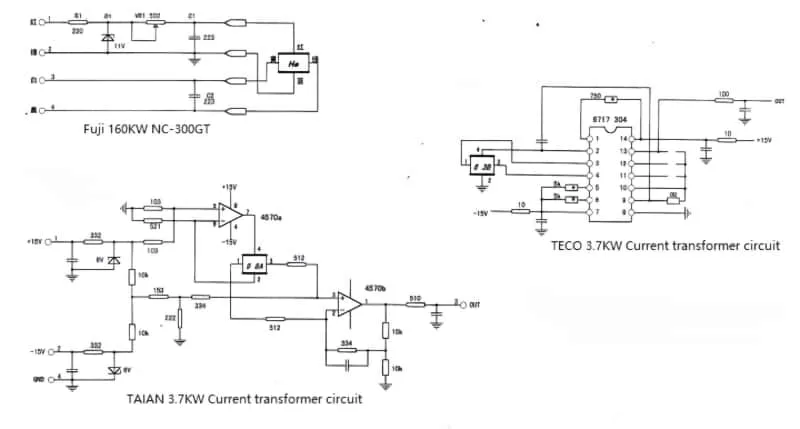
The circuit of the current transformer comprises the Hall element and a precision dual operational amplifier circuit, such as the 4570. For the Hall element to operate, a constant current of approximately 3-5mA must be supplied. In this circuit, the 4570A is configured as a constant current source to provide the necessary mA-level constant current for the Hall element (approximately 5.77mA in this case). This current is applied to pins 4 and 2 of the Hall element.
The induced voltage, which varies with the output current, is present at pins 1 and 3 of the Hall element and is applied to the input terminals 2 and 3 of the 4570B. The three pins are connected to a reference voltage (zero potential point), and any change in the input voltage at the two pins is amplified and output by the 4570B.
Electronic current transformers typically have four terminal components: two terminals supply power to the internal amplifiers (+15V and -15V), while the other two serve as signal output terminals (one grounded and one as the signal OUT terminal). In addition to powering the dual operational amplifier IC4570, the +15V and -15V are further stabilized to form a zero potential point that is introduced into the three pins of the 4570. When the frequency converter is off, the ground measurement at the OUT point should read 0V. During operation, it outputs an AC signal voltage proportional to the output current, typically below 4V.
If an electronic current transformer is damaged, it may output a higher positive or negative DC voltage in the static state (when the frequency inverter is off). This is often due to damage to the internal operational amplifier. When the frequency inverter performs a power-on self-test, it may display a fault code (sometimes not listed in the manual) and refuse to start or even operate with its parameters.
The current transformer circuit of a TECO 3.7kW frequency converter utilizes a programmable operational amplifier chip. Although I have not yet identified the specific model of this chip, modification tests have revealed some of its circuit characteristics. Experimental results indicate that pin 2 is the constant current power supply terminal, pins 3 and 4 are the input terminals of the differential amplifier, and pin 13 is the signal output terminal. By short-circuiting the solder gaps of pins 11, 12, and 13 in a stepwise manner, the amplification factor decreases; conversely, opening the circuit step-by-step increases the amplification factor. This adjustability allows for easier matching of the chip with frequency converters of different power outputs. I successfully applied this current transformer to a 45kW Fuji frequency inverter by taking appropriate measures.
It is important to note that the voltage and current detection signals of the frequency converter may be used by the program to control the output three-phase voltage and current. Therefore, when repairing or modifying the original circuit, it is crucial to maintain the original circuit parameters to ensure proper operation. Whenever possible, it is recommended to use original accessories to repair the frequency converter while preserving the original circuit form.
