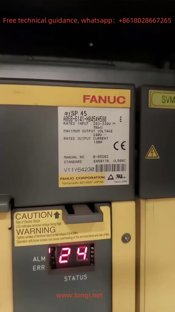
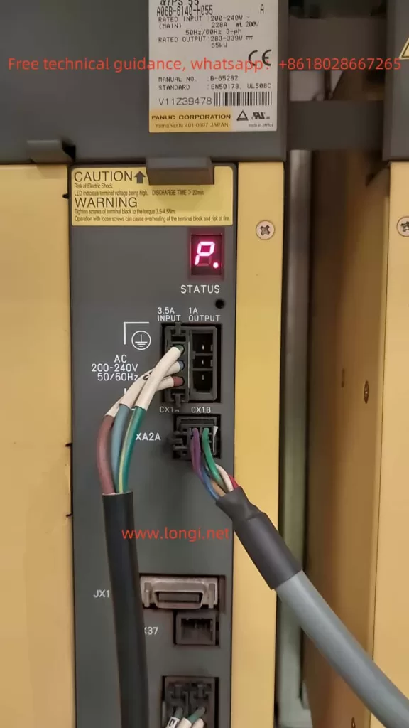
In the maintenance and repair of CNC machine tools, fault alarms are a common occurrence. For equipment using FANUC αi series spindle amplifiers, the AL-24 alarm is a typical code. This article will explore the meaning of this alarm, possible causes, and solutions, providing theoretical support and practical guidance for CNC servo system repairs.

1. Meaning of the AL-24 Alarm
According to FANUC’s official documentation, the AL-24 alarm indicates that the serial communication data between the CNC (Computer Numerical Control system) and the spindle amplifier module contains errors. This alarm typically occurs when there is an abnormality in the communication link between the CNC and the spindle amplifier. It is important to note that this alarm does not necessarily indicate hardware failure; in most cases, it is caused by communication issues or external interference.
Scenarios Triggering the Alarm
- The CNC is powered off while the spindle amplifier remains energized.
- Serial communication is disrupted, causing data transmission errors.
- Communication cables are loose, damaged, or poorly connected.
2. Possible Causes of the AL-24 Alarm
When diagnosing the AL-24 alarm, the investigation should focus on the communication link, cable conditions, and hardware status. Common causes include:
1. Communication Noise Interference
Serial data transmission between the CNC and the spindle amplifier may be disrupted by external electromagnetic noise, resulting in data errors and triggering the AL-24 alarm.
2. Cable Issues or Connection Problems
The communication cable is a critical link between the CNC and the spindle amplifier. Possible issues include:
- Cable aging or internal breakage.
- Loose or improperly secured connectors.
- In the case of fiber optic communication, damaged optical connectors or modules.
3. Bundling of Communication and Power Cables
When communication cables are bundled with spindle or servo motor power cables, high-frequency currents may cause electromagnetic interference, affecting communication stability.
4. Hardware Malfunction
Hardware-related issues that may trigger the AL-24 alarm include:
- Faulty internal circuit boards in the spindle amplifier module (SPM).
- Damaged communication interface boards or modules in the CNC control system.
5. Parameter Configuration Issues
Incorrect communication parameter settings in the spindle amplifier or CNC can also lead to communication failures.

3. Solutions for the AL-24 Alarm
When addressing the AL-24 alarm, follow these steps for systematic troubleshooting:
1. Verify CNC Power Status
Check whether the CNC is properly powered. If the CNC is off, the spindle amplifier cannot establish communication, which is a normal reason for the alarm.
- Action: Ensure the CNC is fully powered and there are no additional alarm codes.
2. Inspect Communication Cables
Communication cables are crucial for the connection between the CNC and the spindle amplifier. Diagnosing cable issues is a key step.
- Steps:
- Inspect the cable’s exterior for damage or aging.
- Ensure connectors are securely plugged in.
- For fiber optic communication, check the cleanliness of the optical connectors and the condition of the optical modules.
- Actions:
- Replace the communication cable and reconnect.
- If optical modules are faulty, contact the supplier for replacement.
3. Address Noise Interference
Communication stability can be compromised by noise interference, particularly when communication cables are bundled with power cables.
- Steps:
- Check the routing of communication cables to ensure they are separated from power and servo cables.
- Use well-shielded cables or add shielding to existing cables.
- Actions: Separate communication cables from power cables to maintain a safe physical distance.
4. Examine the SPM Module
The internal circuit board of the spindle amplifier (SPM) may fail due to aging or external impact.
- Actions:
- Inspect the SPM module for physical damage or burn marks.
- Contact FANUC support for repair or replacement if the module is faulty.
5. Validate CNC Hardware
If the SPM is functioning correctly, check the communication interface boards or modules on the CNC side.
- Actions:
- Replace the relevant communication boards and test.
- Check the CNC’s alarm log for related issues.
6. Correct Parameter Settings
Incorrect communication parameters may prevent successful communication between the CNC and the SPM.
- Actions:
- Reconfigure communication parameters based on the equipment model and manual.
- Ensure communication speed, protocols, and other settings match between the SPM and CNC.
4. Preventive Measures
To reduce the likelihood of AL-24 alarms, consider the following preventive measures:
- Regular Cable Inspection:
- Ensure communication cables are free from aging, breakage, or damage.
- Use durable, high-quality shielded cables.
- Optimize Cable Routing:
- Keep communication cables separate from power lines to avoid interference.
- Routine Hardware Maintenance:
- Inspect the SPM and CNC hardware regularly and replace aging components promptly.
- Clean amplifier and cable interfaces to prevent dust accumulation.
- Environmental Control:
- Minimize strong electromagnetic interference around the equipment.
- Provide adequate cooling for amplifiers and control cabinets.
Conclusion
The AL-24 alarm, a common fault code in FANUC αi series spindle amplifiers, primarily reflects communication abnormalities between the CNC and the spindle amplifier. By understanding its meaning, identifying causes, and following a structured troubleshooting process, maintenance personnel can quickly resolve the issue. Additionally, implementing preventive measures can significantly reduce the occurrence of such alarms, ensuring long-term stability and performance of the equipment.
