
In movies and TV shows, when a Taoist from Maoshan encounters an urgent and difficult situation, he often recites a curse: “The Supreme Old Lord is as sick as a law… If something difficult happens, it should be solved by the curse.”. If there is an urgent VFD repair, we can also recite a few mantras and find the “smart” method for quick maintenance.
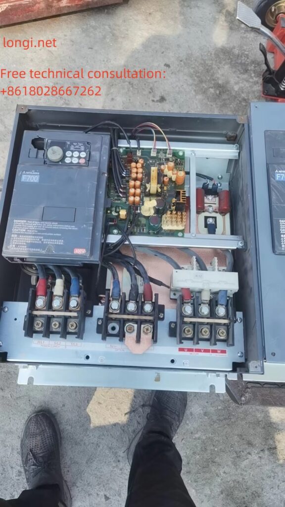
On a rainy day, thunder and lightning flash. The door of the maintenance department was suddenly forcefully pulled open by someone. Three or four strong men, carrying an unmarked 75kW VFD, strode in and asked, “Our workshop is for refining silver, and the frequency converter was damaged by lightning.”. Urgent use! Can the malfunction be detected and repaired within three hours. Okay, don’t bargain; If you don’t have diamond, don’t take on porcelain work. Let’s quickly change the door. It’s not just you who can fix VFD.
This VFD may be able to earn half a month’s salary. No second words, fight!
I roughly inquired about the damage to VFD. During operation, due to lightning strikes introduced from the three-phase power supply, even the main power switch in the workshop tripped. Close the power switch of VFD again, there is a popping sound, and the switch jumps open again.
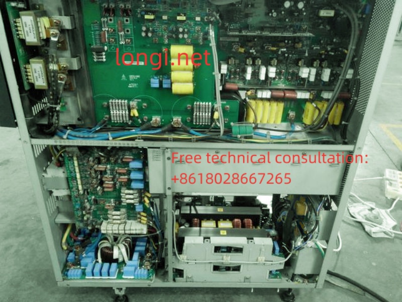
In this situation, there must be a short circuit fault in the three-phase rectifier circuit of VFD. Instead of being busy with power on, use the resistance range of the multimeter’s R, S, T power input terminals and U, V, W output terminals to determine the resistance of the main circuit with the P and N terminals of the DC circuit. There is a short circuit phenomenon in the measurement, rectification, and inverter power circuits. Detailed inspection after disassembly revealed that two rectifier modules were damaged, one inverter module was broken, and the energy storage capacitor was tested and found to be fine.
The repairman asked, “Isn’t it enough to replace these three faulty parts?”? Answer: Don’t be impatient. Due to the introduction of lightning strikes within VFD, the situation is complex and the quality of the control circuit board is unclear. If the inverter power module is damaged, it will have an impact on the driving circuit. If there is a hidden fault, the replacement module will be damaged again. Further investigation is needed to determine whether to replace the module.
Key contents to be checked: 1. Whether the CPU motherboard is damaged, especially whether the CPU chip is damaged; 2. Inverter pulse transmission circuit, including driving circuit and inverter pulse front-end circuit. Especially for the driving circuit, the triggering terminal circuit of the IGBT should be checked for any open circuit or negative pressure power supply; 3. Other circuits, whether the control terminal circuit has been damaged by lightning strikes, and whether the control circuit (fault detection circuit, etc.) has been damaged.
The key among them is that as long as the CPU can output six inverter pulses, repairing other faults should be easy.
(A) Power on the switch power supply or troubleshoot the switch power supply:
Remove the CPU motherboard and power/driver board from the inverter casing and place them on the maintenance workbench. Power should be supplied to the switch power supply of the circuit board first, or the switch power supply should be repaired first to facilitate troubleshooting of other circuits. I tested the power supply terminals of the switching power supply and the filtering capacitor at both ends of the secondary rectification circuit of the switching transformer, and there was no short circuit phenomenon. It is possible to power on the switching power supply. The power supply source of the Shunxia switch power supply is directly taken from the 530V DC circuit of the DC circuit. If measured on the circuit, the drain (collector) of the switching transistor of the switching power supply should be connected to the P-terminal of the DC circuit, and the source (emitter) should be connected to the N-terminal of the DC circuit.
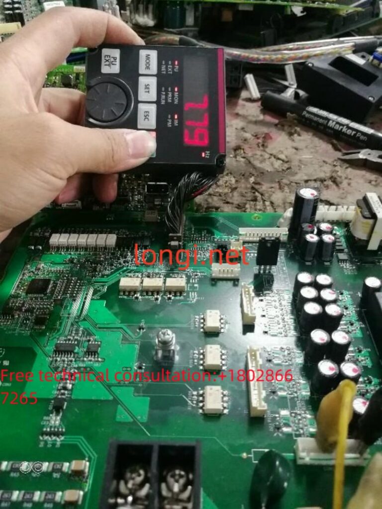
Alright, connect the 500V DC maintenance power supply to the power supply terminal of the switch mode power supply (pay attention to polarity, it can be bad if connected in the opposite direction), it’s not bad! The corresponding changes in characters during the startup period on the operation display panel indicate that the switch power supply and the peripheral circuit of the CPU chip are basically working normally, and the CPU is also good.
(B) Release the OH (module overheating) fault alarm:
After the startup character on the operation display panel flashes, an OH (module overheat) fault code is reported. Press the RST reset button on the operation display panel, OH disappears once, and it is displayed again, unable to reset. At this time, the frequency converter is in a fault locked state and refuses to accept operating signals, making it impossible to detect whether the inverter pulse transmission circuit is normal. The OH alarm must be disarmed. Observing the main circuit, two normally closed contact type thermal relays are installed near the heat sink module. When the circuit board is disconnected from the main circuit, it is equivalent to the temperature sensor’s normally closed point breaking, reporting an overheat signal. Find the corresponding temperature sensor terminals on the circuit board, short circuit them with wires or solder, and there should be no OH fault reported. Some frequency converters use thermistors to detect the temperature of the module. When the terminal is open, an OH fault will also be reported. Simply remove the temperature sensor and insert it into the corresponding terminal on the control board. Still report OH, don’t worry, there may be related temperature detection signals sent to the control board.
Observe the socket and lead of the cooling fan, which is a three wire fan. Two wires are the positive and negative terminals of the 24V power supply, and one wire is the signal wire. Return the operation/fault signal to the control board. If you remove the fan and plug it back into the control board, it would be too troublesome. There is a simple way to find the positive and negative wires, and test connecting the third wire to the positive and negative power supply terminals respectively. When this wire is connected to the positive power supply terminal, the OH fault code on the operation display panel disappears.
(C) Release Uu (undervoltage) and input phase loss alarm:
After a brief moment of joy, the operation display panel showed another Uu (undervoltage) fault, and the frequency converter was still in a fault locked state.
When the switching power supply adopts 265V (or 300V) DC power supply, we disconnect the control board from the main circuit and separately supply 265V (or 300V) DC power to the switching power supply. Most of the operation panels will report Uu faults (some frequency converters, DC circuit voltage detection signals are obtained in the secondary rectification circuit of the switching transformer, so Uu faults will not be reported), because the input of the DC circuit detection circuit is in an open circuit state, and the circuit output is an undervoltage signal. From the DC circuit voltage introduction terminals (P, N terminals), find the input resistance network of the DC circuit detection circuit, a large high resistance circuit, seven or eight phases in series, because the switching power supply is 300V DC power supply at this time, directly introduce it into the DC circuit voltage detection circuit, or report a Uu fault. Short circuit a few resistors in the input resistor network (if there are 8 resistors, 3 can be short circuited for testing) to adapt to the 300V voltage output range.
Introduce a DC voltage artificially into the DC detection circuit and modify the detection to meet the requirements of the voltage input range. Some frequency converters may not report Uu faults, but they may also report “charging contactor not engaged fault”, while others may still report Uu faults. Don’t worry, there may be related voltage detection signals sent to the control board.
The charging contactor cannot be removed and connected to the control board in the main circuit. The frequency converter often has a status detection circuit for the auxiliary contact of the charging contactor. Due to the disconnection between the control board and the main circuit, the CPU detects that the auxiliary contact of the charging contactor is always in an open circuit state after the control board is powered on, and will also report Uu or “charging contactor not engaged fault”. Find the lead terminals of the auxiliary contacts of the charging contactor from the main circuit, determine the corresponding socket terminals of the control board, short circuit or solder the lead terminals with wires, and tell the CPU that the charging contactor has been closed.
After short circuiting the lead terminals of the auxiliary contacts of the charging contactor, the operation display panel finally stopped tripping Uu fault.
(D) Release OC (module overcurrent or output short circuit) fault alarm:
After a brief moment of joy, the fault code no longer jumps. From the display on the operation display panel, it appears that the inverter has entered standby mode and can be started for maintenance of the inverter pulse transmission channel. Press the start/stop button on the operation display board, but the frequency converter does not respond. The user may have set it to terminal operation. Ask the repairman, and indeed. For the convenience of operation, if the control parameters can be modified (if there is a frequency converter manual at hand), or the operation can be changed to start/stop and frequency adjustment using the control panel; If it is inconvenient to modify the parameters, you can try inputting the operation and frequency signals from the control terminal. Measure the frequency and adjust the power supply to 10V for normal output. Short circuit it to the input end of the 0-10V frequency signal to input the highest operating frequency command for the frequency converter (it is not troublesome, but can also be adjusted with an external potentiometer). Short circuit the forward running terminal to the digital common terminal for a startup test, and the operation display panel will display an OC fault code. Of course, the frequency converter is still in a fault locked state and cannot accept the operation.
The power module cannot function without various comprehensive protections, but at this point, I really feel that these fault alarms are troublesome. However, if they are not resolved, the inverter pulse transmission circuit cannot be repaired. Slowly, when an alarm signal is issued, it will be tracked and released. Generally, when the control circuit board is disconnected from the main circuit, three or four faults will jump out. Pay attention to finding the source of each signal from each plug-in terminal, or from the input and output sides of the plug-in terminal or the optocoupler that transmits the signal, use wire short circuiting method to force the CPU to input a “normal” signal and release the fault lock state.
The OC signal is mostly sent back to the CPU by the IGBT voltage drop detection circuit (IGBT protection circuit) of the driving circuit. When there is a fault in the output current detection circuit, an OC fault will also be reported, but this situation is relatively rare. Following the principle of easy first and difficult later, the OC signal returned by the driving circuit can be released first, and then the output current detection circuit can be detected.
The commonly used ICs for driving circuits are PC923, PC929, and A316J. The former uses the OC signal output by the internal IGBT protection circuit of PC929, which is then sent to the CPU through an external optocoupler. Find the optocoupler connected in parallel with PC929, and short-circuit its input side with a soldering iron to release the OC alarm (it is a fast method, not a good method); The latter, the 5 pins of the driver chip A316J are the OC signal output pins, which are separated from the copper foil strip to isolate the transmission of OC signals; But this method is not very convenient. Although it blocks the transmission of OC signals, it is advisable to check whether the CPU and the front-end inverter pulse transmission circuit have output inverter pulse signals. However, the drive IC itself is still in a fault locked state, which is not conducive to repairing the drive circuit.
A good solution is to manually input an IGBT “normally open” signal to the IBGT detection circuit, so that the driving IC itself no longer reports OC faults during the input inverter pulse period. The general driving circuit is implemented by the lower three arm driving circuit to detect the voltage drop of the IGBT transistor. The trigger terminal is used to short circuit the output end of the inverter pulse to the OV end of the driving power supply (the connection point with the N end of the main circuit), which is also relatively easy to find.
(E) Perform maintenance on the drive circuit:
Finally, the frequency converter can accept the startup signal. Looking at the gradually increasing output frequency indicator displayed on the control panel, I breathed a sigh of relief, indicating that the CPU circuit and control terminal circuit are both good. The repair of the frequency converter is basically without any suspense.
Measure the six inverter pulse input terminals of the driving IC, and there is a significant voltage change in the start and stop states. The six inverter pulses from the CPU motherboard have been input into the driving circuit intact and undamaged. The CPU motherboard is good! Measure the output status of six inverter pulses from the pulse output terminals of the power/driver board, and check if the negative cutoff voltage is normal and if there are normal pulse outputs. Does the voltage amplitude and current amplitude of the pulse output meet the normal requirements? Due to the damage of the IGBT causing impact on the driving IC, there are two driving circuits that cannot output pulse signals normally. This is simple. A power amplifier consisting of a driver IC and a rear stage consisting of two transistors was found to have damaged components. After replacement, all six inverter pulses were output normally.
The maintenance process has been declared completed. The entire maintenance process took exactly 45 minutes. After the maintenance is completed, it seems like we won a small battle so happily. The next task is to replace and purchase modules.
Throughout the entire maintenance process, four strong men were eagerly staring at the frequency converter, including one electrician who was extremely excited: he had learned and really had real skills. I didn’t expect it to be so troublesome. Blowing up a module is not as simple as replacing it.
To the repairman, the control circuit has been repaired, but there is no power module at hand. Then, you can go to the same city to “search” for it. If not, it will only be sent from outside the city. You will have to find your own way to delay your silver refining.
The four repairmen all laughed and said, “No problem, no problem. Please hurry up and send the package.”.
The various methods used during the maintenance process are scattered in my other blog posts, but they belong to local maintenance methods. For actual maintenance, sometimes there is a small gap between what is explained by a single unit circuit, which is difficult to understand. Through the description of a specific maintenance example process in this article, the application of various maintenance methods can be integrated and integrated.