
Analysis of IGBT Module and Driver Faults in Variable Frequency Drive Repairs
In the field of industrial automation, variable frequency drives (VFDs), as key equipment for motor speed control, are crucial for stable operation. However, due to the complex and varied working environments, faults in the IGBT modules and drive circuits within VFDs occasionally occur, causing significant impacts on production. This article delves into the identification, analysis, and handling processes of IGBT module and driver faults through three practical repair cases, aiming to provide valuable references for relevant technicians.
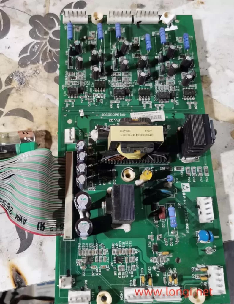
Case 1: Phase Deviation Fault in Dongyuan 7300PA3.7kW VFD
Fault Phenomenon: After powering on, a Dongyuan 7300PA3.7kW VFD had outputs on all U, V, and W phases, but with severe phase deviation.
Fault Diagnosis: Initially suspected as a drive circuit abnormality or IGBT module damage. Measurements revealed an open circuit in the upper arm diode of the U-phase in the inverter circuit. Typically, the IGBT transistor paralleled with this diode was also burnt due to short-circuit current, and the paralleled diode was damaged by the impact.
Repair Process:
- After removing the damaged SPIi12E IGBT module, clear all the module pins and prepare to test the six drive circuits.
- Upon powering on, the VFD immediately reported an overheating fault, with the CPU locking the drive pulse output, preventing drive circuit quality detection.
- Two terminals labeled T1 and T2 on the circuit board, suspected as internal overheating alarm outputs of the module, were observed. By connecting a 5V power supply through a resistor, the other end grounded. When these terminals were left open, the T1 terminal output a high-level module overheating signal through a pull-up resistor, triggering protective shutdown.
- After short-circuiting the T1 and T2 terminals, powering on no longer resulted in protective shutdown. It was found that the U-phase upper arm IGBT drive circuit had no trigger pulse output. After replacing the drive circuit IC/PC923, the six-pulse output returned to normal.
- A new IGBT inverter module was installed, the short-circuit wire between T1 and T2 was removed, and the VFD operated normally after powering on.
Experience Summary: When an IGBT tube is damaged, the corresponding drive IC is often damaged by the impact as well. Before replacing the new module, be sure to check the drive IC in the same branch to avoid damaging the new module again due to drive circuit abnormalities.
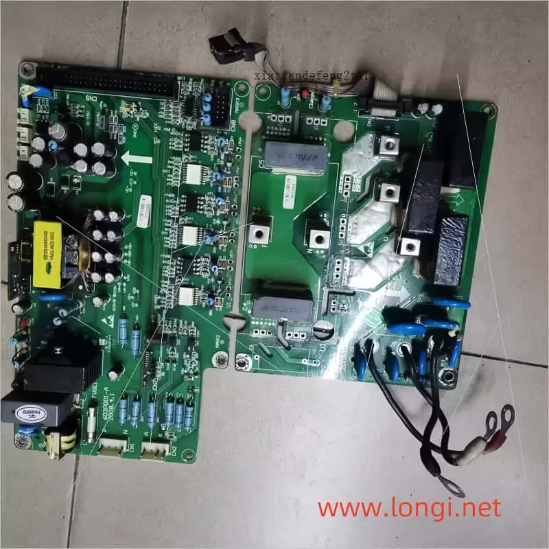
Case 2: Repair of Lightning-Damaged Alpha 18.5kW VFD
Fault Phenomenon: An Alpha 18.5kW VFD was damaged by lightning, with the CPU motherboard reporting a 2501 error and panel operations failing.
Fault Diagnosis: Lightning caused damage to the CPU and surrounding communication circuits.
Repair Process:
- Temporarily ignoring the CPU motherboard issue, repair the drive board first. It was found that six A316J chips were responsible for six drive pulse outputs, with three upper arm pulse drive circuits damaged.
- As an alternative, three A316J chips (for three-phase lower arm drives) were used as three-phase OC signal alarm outputs, and the remaining three were replaced with 3120 (identical to PL250V) to drive the optocoupler ICs.
- The new ICs were adapted and soldered, and the input circuit was adjusted to ensure normal operation of the new ICs.
- After replacing the new CPU motherboard, the static output voltage and dynamic pulse output of the six drive circuits were tested and found to be normal.
- The damaged IGBT module was replaced, and the VFD resumed normal operation.
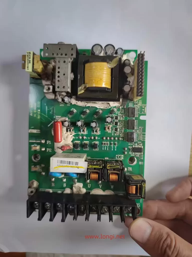
Case 3: Repair of Phase Deviation in a 7.5kW VFD
Fault Phenomenon: A user reported that a 7.5kW VFD had output but could not operate normally, with phase deviation present.
Fault Diagnosis: It was found that one of the six drive circuits was abnormal, with the drive IC model being PC929 (or A4503?). Measurements showed no pulse output at the input and output terminals of the drive IC.
Repair Process:
- Suspecting a fault in the CPU’s internal pin circuit, the input terminal of the PC929 was disconnected, and it was found that the voltage at the CPU’s pulse output terminal increased. However, when the drive IC was connected, the voltage dropped to nearly 0V.
- It was analyzed that the CPU directly drove the photoconductive tube, and long-term high-current output led to aging faults in the output stage. It was decided to enhance the signal voltage through an external amplification circuit.
- An amplification circuit was constructed using two NPN-type transistors and resistors to amplify the CPU’s pulse signal before inputting it to the drive IC.
- After powering on, the six-pulse output was normal, and the inverter module was powered on, with normal three-phase voltage output.
Experience Summary: For aging faults in the CPU’s output stage, amplifying the signal voltage through an external circuit is an effective repair method, which not only saves repair costs but also shortens repair time.
In summary, IGBT module and driver faults are common challenges in VFD repairs. Through meticulous fault diagnosis, reasonable repair strategies, and innovative repair methods, these issues can be effectively resolved, ensuring the stable operation of VFDs. It is hoped that the sharing in this article can provide valuable references and insights for technicians.