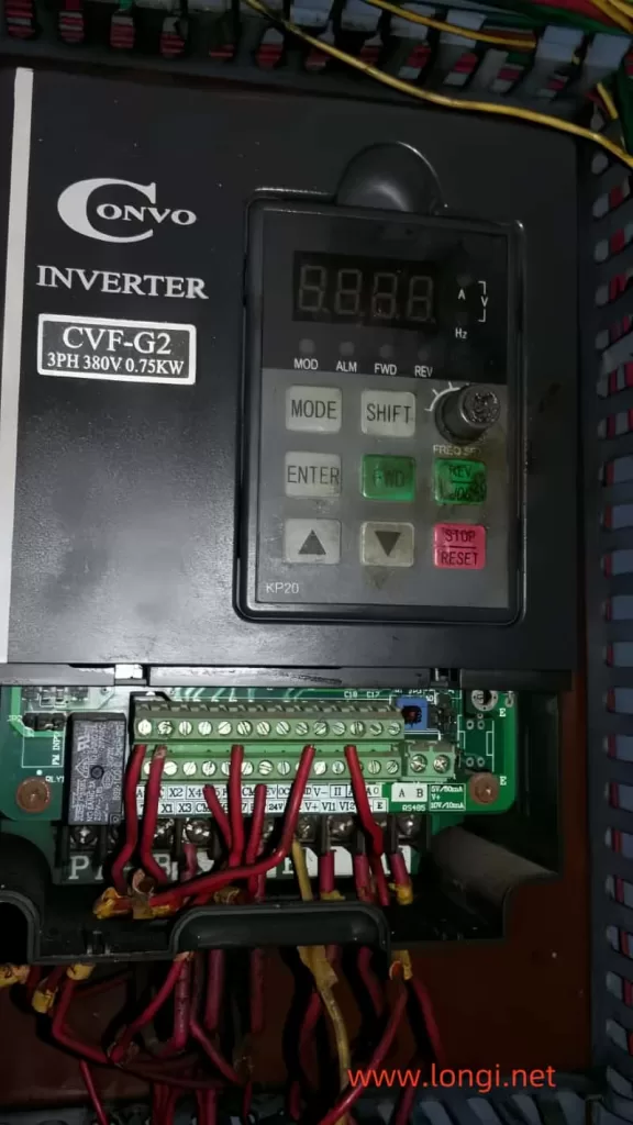
Title: Troubleshooting Guide for CVF-G1 Switching Power Supplies in CONVO Frequency Converters
Introduction:
We recently received three CVF-G1 frequency converters from Kangwo, all exhibiting identical issues: no output from the switching power supply and no screen display. Given that the power supply IC in these machines is a 3844B, and considering the rarity of this IC causing failures in multiple units simultaneously, we embarked on a troubleshooting journey focusing on the peripheral circuits.

Understanding the Switching Power Supply:
A typical switch-mode power supply comprises several key branches:
- Power-On Start Branch: This consists of a series of high-resistance resistors that, upon powering on, direct 500V DC to the 3844B power supply pin, initiating the switch tube’s starting voltage.
- Positive Feedback and Working Power Supply Branches: These are composed of feedback windings and rectifier filtering circuits, varying between machines in configuration.
- Voltage Stabilizing Branch: Powered by a secondary 5V supply, this branch compares 5V voltage changes against a reference, feeding back variables to the 3844B via an optocoupler. Notably, the CVF-G1 model feedback is derived from the primary side.
Conditions for Circuit Oscillation:
For the circuit to oscillate, the following must be met:
- The 500V power supply circuit must be functional, delivering DC voltage to the switch’s drain through the main winding.
- The power-on start branch must supply an adequate starting voltage (current).
- The positive feedback and working power supply branches must provide the necessary feedback voltage (current) and working power.
- The load side must be free of short circuits, as these prevent the establishment of sufficient feedback voltage, halting oscillation.
Troubleshooting Approach:
To pinpoint the fault, we began by isolating the voltage stabilizing branch to check if the circuit could oscillate without it. We ensured safety by implementing voltage reduction and disconnecting circuits susceptible to voltage damage. If the circuit oscillated, it suggested that the oscillation conditions were generally met, shifting our focus to the voltage stabilizing branch for further investigation. If not, the issue lay within the oscillation circuit itself.

Findings and Repairs:
- Machine A: All four branches and 3844B peripherals checked out normal. Replacing the 3844B with a 3845B restored power output.
- Machine B: Despite replacing the IC with a 3845B, oscillation failed to initiate. All branch components appeared normal. However, paralleling a 200k resistor with the existing 300k resistor in the power-on start branch resolved the issue, indicating a subtle performance shift in one or more components affecting electrical parameters.
- Machine C: The fault was traced to the 3844B IC, and replacing it resolved the issue.
Analysis of Machine B’s Unique Fault:
Machine B’s fault was particularly intriguing. No obvious defective parts were found, yet it failed to oscillate until the starting branch’s resistance was adjusted. This suggests minor changes in component performance, such as reduced switching tube amplification, moisture-affected transformer Q values, increased 3844B output resistance, or slight variations in resistance/capacitance components. Identifying these precise causes can be challenging, but they all lead to one outcome: ineffective switch tube activation. Adjusting the starting branch’s resistance proved to be an effective solution, highlighting the importance of adequate starting current for circuit oscillation.
Conclusion and Recommendations:
Based on our experience, an efficient repair strategy for similar issues involves:
- Verifying the switch tube’s integrity and the general functionality of the four branches.
- Conducting a parallel resistance test on the starting branch.
- If unsuccessful, replacing the 3844B IC.
- If issues persist, conducting a thorough circuit inspection.
Often, issues are resolved during the initial tests, emphasizing the importance of a systematic approach to troubleshooting. Additionally, considering the role of starting current in circuit oscillation, adjusting the starting branch’s resistance may offer a simple yet effective solution in many cases.
