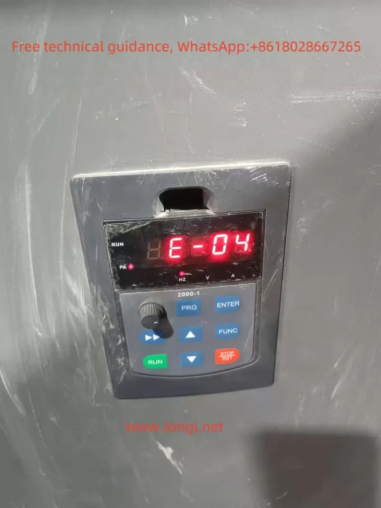
I. Introduction to the Operation Panel of the Nengshi NSA2000 Series Inverters

The operation panel of the Nengshi NSA2000 series inverters features intuitive and powerful control functions, capable of meeting the demands of various industrial applications. The main function keys on the operation panel include:
- RUN: The inverter run key, used to start the inverter.
- REV/JOG: The reverse/jog key, which can be set to reverse or jog functions according to parameters.
- STOP/RST: The stop/reset key, used to stop the inverter or reset it in case of a fault.
- PRG: The mode switch key, used to switch the working mode of the operation panel.
- ENTER: The confirmation key, used to confirm the current status or store parameters.
- ▲/▼: The data modification keys, used to modify function codes or parameter values.
- SHIFT: The data bit switch key, used to select the bit to be modified when modifying data.
How to Restore Factory Settings (Initialize Parameters)
- With the inverter in the stopped state, press the PRG key to enter the parameter query mode.
- Press the PRG key again to enter the parameter modification mode.
- Use the ▲/▼ keys to select the function parameter F3.01.
- Press the ENTER key to enter the parameter modification state.
- Set the parameter value to 1 and press the ENTER key to confirm, restoring the inverter to factory settings.
How to Set Passwords and Parameter Write Protection Functions, and How to Eliminate Passwords
- Setting a Password: Modify the function parameter F3.03 to set a 4-digit numeric password within the range of 0000-9999.
- Parameter Write Protection: Function parameter F3.02 is used to set parameter write protection, allowing choices between allowing modification of all parameters, only allowing modification of frequency settings, or prohibiting modification of all parameters.
- Eliminating a Password: Reset the value of function parameter F3.03 to 0 to eliminate password protection.
Function and Setting Method of Jump Frequencies
Jump frequencies are used to avoid the mechanical resonance points of load devices, preventing equipment damage or performance degradation due to resonance. The setting method is as follows:
- Use the ▲/▼ keys to select function parameters F2.36, F2.37, F2.38, F2.39, F2.40, and F2.41, which are used to set the three jump frequencies and their corresponding jump ranges.
- Press the ENTER key to enter the parameter modification state, use the ▲/▼ keys to set the desired jump frequencies and ranges.
- After setting, press the ENTER key to confirm.
II. Realization of Terminal Forward/Reverse Control and External Potentiometer Frequency Control Functions
Terminal Forward/Reverse Control
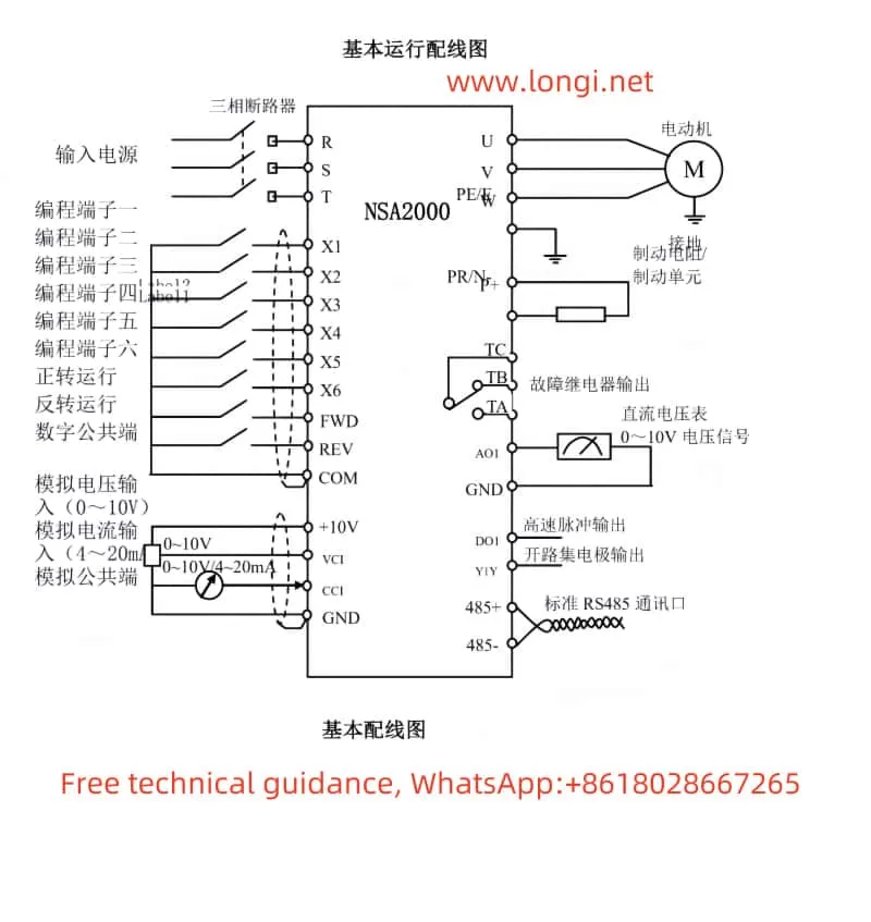
Terminal forward/reverse control is achieved by controlling the on/off states of the FWD and REV terminals. The parameters that need to be set include:
- F0.04: Operation command channel selection, set to 1 to control via terminals.
- F4.06: FWD/REV terminal control mode, select the appropriate control mode according to actual needs (such as two-wire or three-wire mode).
In terms of wiring, connect the external control switches to the FWD and REV terminals respectively, and ensure that the common terminal COM is correctly connected.
External Potentiometer Frequency Control
The external potentiometer frequency control function allows users to change the output frequency of the inverter by adjusting the resistance value of an external potentiometer. The parameters that need to be set include:
- F0.01: Frequency setting channel selection, set to 0 to use the potentiometer on the operation panel.
- If using an external potentiometer, set F0.01 to 4 (VCI analog setting) or 5 (CCI analog setting), and configure the input range of VCI or CCI (F5.00-F5.03) according to actual conditions.
In terms of wiring, connect the three terminals of the external potentiometer to the VCI (or CCI), GND, and +10V (or 0V) terminals of the inverter.

III. Meaning and Handling of E-04 Fault
Meaning of E-04 Fault
The E-04 fault indicates overvoltage during the acceleration process of the inverter. This is usually caused by abnormal grid voltage, restarting a rotating motor, or excessively short deceleration time.
Handling Method
- Check the Input Power Supply: Ensure that the grid voltage is stable and meets the operating requirements of the inverter.
- Avoid Restarting a Rotating Motor: If it is necessary to start a rotating motor, set it to DC brake start.
- Extend the Deceleration Time: Appropriately extend the deceleration time of the inverter based on actual conditions to reduce overvoltage.
Fault Repair
If the above methods cannot resolve the E-04 fault, further inspection and repair of the inverter may be required. It is recommended to contact professional after-sales service personnel or a technical support team for troubleshooting and repairs. During the repair process, ensure that the power supply to the inverter is cut off and operate in accordance with relevant safety regulations.
Conclusion
The Nengshi NSA2000 series inverters feature a rich set of operation panel functions. Through reasonable parameter settings and wiring configurations, various control functions can be realized. When handling E-04 faults, first check the input power supply and the operating status of the inverter, and take corresponding measures based on actual conditions. If further repairs are needed, it is recommended to contact a professional technical support team. Through proper use and maintenance, the Nengshi NSA2000 series inverters will provide users with stable and reliable variable frequency speed regulation solutions.
