I. Functions of the DCS550 Control Panel and Local Start/Speed Adjustment
1.1 Control Panel Overview The DCS550 control panel (DCS Control Panel) is used for monitoring, operation, and parameter configuration of the drive. Its main features include:
- Start/Stop Button: Used to start or stop the drive.
- LOC/REM Button: Switches between Local (LOC) and Remote (REM) control modes.
- Navigation and Confirm Keys: Used for navigating parameter menus and adjusting settings.
- Display Screen: Displays operational status, alarm messages, and parameter values.
- Quick Menu: Provides quick access to key parameter settings and fault diagnostics.

1.2 Local Start and Speed Adjustment
- Ensure the drive is in Local mode (display shows “L”).
- Press the Start button to run the drive.
- Use the navigation keys to adjust the speed setpoint.
1.3 Field Circuit Parameter Configuration
- The field voltage output can be measured across the F+ and F- terminals. Set the following parameters based on the motor’s rated values:
FldCtrlMode (44.01): Configure the field control mode as “Automatic” or “Constant Voltage.”FldMaxCur (44.02): Set the maximum field current.FldVoltNom (44.03): Set the nominal field voltage.
1.4 Armature Circuit Parameter Configuration
- Key parameters for the armature circuit include:
ArmVoltMax (43.01): Set the maximum armature voltage.ArmCurrMax (43.02): Set the maximum armature current.RampUp/RampDown (42.01/42.02): Configure acceleration and deceleration times for current and speed.

1.5 Speed Feedback Parameter Configuration
- Speed feedback can be provided via encoder signals or analog signals:
SpeedRefSel (20.02): Select the speed reference signal source.EncoderPPR (45.03): Set the pulses per revolution (PPR) for the encoder.
1.6 Auto-Tuning of Parameters
- Follow these steps for parameter auto-tuning:
- Ensure the motor and load are properly connected.
- Access the auto-tuning menu and enable
AutoTune (22.01). - The system will automatically adjust control parameters and display “OK” upon completion.
1.7 Fan Parameter Configuration
- Fan control can be enabled or disabled using parameter
MotFanCtrl (10.06). FanTest (10.07): Test the fan to ensure proper operation.FanCtrlMode (10.08): Select “Automatic” or “Continuous” control mode.
II. How to Achieve Forward and Reverse Control in Remote Mode
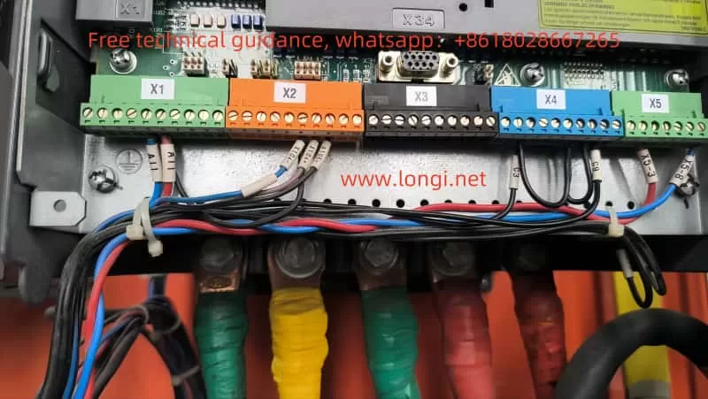
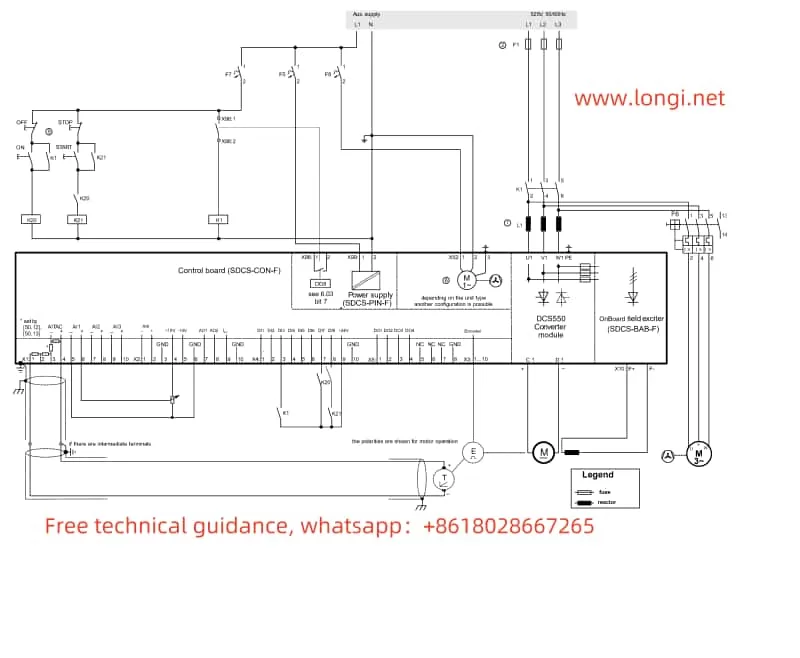
2.1 Wiring Instructions
- Forward/Reverse Control Signals:
- Connect the forward and reverse signals to DI1 and DI2 terminals on X4 (used for forward and reverse operations, respectively).
- If an external emergency stop is required, connect the signal to DI5.
- Speed Reference Signal:
- Use an analog input and connect the speed reference signal to AI1 on X2.
2.2 Parameter Configuration
- Remote Control Mode:
- Set
CommandSel (10.01)to “MainCtrlWord” to enable remote control commands.
- Set
- Forward/Reverse Logic:
- Configure
RevEnable (20.03)to allow reverse operation. - Assign forward/reverse input signals to DI1/DI2.
- Configure
- Speed Reference Configuration:
- Set
Ref1Sel (11.03)to AI1 for speed reference input.
- Set
- Acceleration/Deceleration Times:
- Adjust
RampUp (42.01)andRampDown (42.02)as needed for the application.
- Adjust

III. Fault Codes, Their Meanings, and Solutions
The DCS550 displays fault codes to indicate abnormal conditions. Below are common fault codes and their troubleshooting methods:
3.1 Common Fault Codes
- F001: Overcurrent Fault
- Cause: Armature current exceeds the maximum set value.
- Solution:
- Check if the motor load is too heavy.
- Verify the correctness of the armature circuit wiring.
- Decrease acceleration/deceleration times.
- F002: Overvoltage Fault
- Cause: Armature voltage exceeds the allowable range.
- Solution:
- Check the stability of the power supply voltage.
- Increase the capacity of the DC power filter.
- F003: Encoder Fault
- Cause: Encoder signal lost or abnormal.
- Solution:
- Verify encoder wiring and power supply.
- Check if the parameter
EncoderPPR (45.03)is correctly configured.
- F004: Field Overcurrent
- Cause: Field circuit current exceeds the set value.
- Solution:
- Inspect the wiring of the field circuit.
- Verify that the field parameters match the motor specifications.
- F005: Fan Fault
- Cause: The fan failed to start or stopped unexpectedly.
- Solution:
- Check the fan’s power supply and terminal connections.
- Use
FanTest (10.07)to test the fan’s functionality.
3.2 General Fault Troubleshooting Recommendations
- Check the alarm messages on the control panel and note the fault codes.
- Refer to the troubleshooting section of the user manual for detailed instructions.
- Use the DriveWindow Light software to access detailed fault diagnostics and suggestions.
IV. Conclusion
This guide provides a detailed overview of the operation, parameter configuration, remote control, and fault troubleshooting of the ABB DCS550 DC drive. During use, consider the following key points:
- Ensure electrical wiring complies with the manual to avoid errors.
- Familiarize yourself with the control panel functions and adjust parameters to meet application needs.
- Regularly inspect the equipment’s operational status and promptly address alarm messages.
For complex issues, contact ABB technical support or refer to the relevant sections of the user manual for further diagnosis and resolution.
