
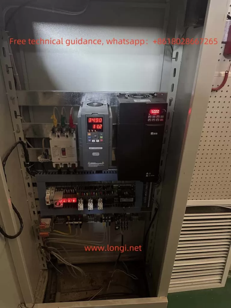
The Botain A900 series inverter is a high-performance, feature-rich industrial-grade device widely used in various industrial scenarios. To help users better understand and operate this inverter, this article provides a detailed introduction to the control panel functions, parameter initialization, password setting and locking, parameter copying, external terminal control, and fault code analysis and troubleshooting methods.
1. Introduction to the Control Panel Functions
The A900 series inverter’s control panel is designed intuitively, with the following main buttons and display areas:
- RUN Key: Starts the inverter operation.
- STOP/RESET Key: Stops the operation or resets faults.
- Arrow Keys (Up, Down, Left, Right): Used for browsing parameters or adjusting settings.
- ENTER Key: Confirms parameter settings.
- ESC Key: Exits the current menu.
- LED Numeric Display Screen: Displays current frequency, operating status, fault codes, etc.
How to Restore Parameter Initialization?
To reset the inverter to factory settings, follow these steps:
- Enter the parameter setting mode and locate parameter
P0-00. - Set
P0-00to1and pressENTERto confirm. - The inverter will automatically restore all parameters to their factory default values.
How to Set Passwords and Lock Parameters?
To prevent parameters from being accidentally operated or changed, follow these steps to set a password:
- Locate parameter
P0-14and set a 4-digit password. - After confirmation, some parameters will be locked.
- To unlock, enter the correct password in
P0-15.
How to Copy Parameters to Another Inverter?
The parameter copy function allows users to quickly transfer the settings of the current inverter to another one. Follow these steps:
- Insert the control panel into the current inverter and enter the parameter setting mode.
- Set
P0-50to1to save parameters to the panel. - Insert the control panel into the target inverter, set
P0-50to2, and load the parameters from the panel to the inverter. - Once parameter copying is complete, the inverter will reset automatically.
2. External Terminal Control and Speed Adjustment Settings
How to Achieve External Terminal Forward/Reverse Control?
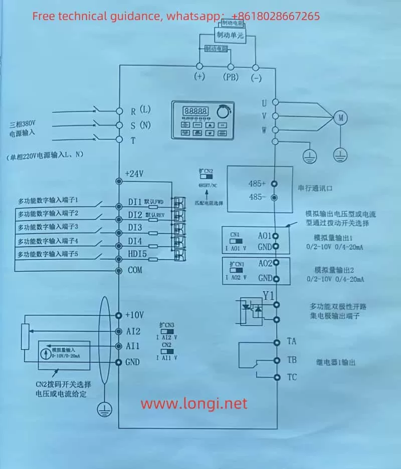
To control forward/reverse rotation via external terminals, complete the following wiring and parameter settings:
- Wiring Requirements:
- Forward Control: Connect the control signal to terminal
FWD. - Reverse Control: Connect the control signal to terminal
REV. - Common Terminal: Connect to terminal
COM.
- Forward Control: Connect the control signal to terminal
- Parameter Settings:
- Set
P0-02to1(External Terminal Control Mode). - Set
P3-01andP3-02for the logic input definitions of forward and reverse rotation.
- Set
How to Achieve Frequency Adjustment with an External Potentiometer?
- Wiring Requirements:
- Connect the middle terminal of the potentiometer to
AI1(Analog Input 1). - Connect the two side terminals of the potentiometer to
+10VandGND, respectively.
- Connect the middle terminal of the potentiometer to
- Parameter Settings:
- Set
P0-03to1(Analog Voltage Input). - Adjust
P1-01andP1-02to the minimum and maximum frequency values to ensure that the potentiometer adjustment range meets actual needs.
- Set
Through the above settings, you can achieve forward/reverse control via external terminals and adjust output frequency via the potentiometer for precise speed control.
3. Fault Codes and Troubleshooting Methods
During operation, the inverter may encounter faults for various reasons. Below are common fault codes, their meanings, and troubleshooting methods:
| Fault Code | Fault Description | Troubleshooting |
|---|---|---|
| E001 | Overcurrent Protection | Check if the motor is overloaded or if the output line is short-circuited. |
| E002 | Overvoltage Protection | Check if the power supply voltage is abnormal or if feedback is too high. |
| E003 | Undervoltage Protection | Check if the power supply voltage is too low or if there is a loose connection. |
| E004 | Overtemperature Protection | Check if the inverter’s cooling system is working properly and clean the heat sink. |
| E005 | Phase Loss Protection | Check if the three-phase power input is normal and if the motor has a disconnection. |
| E006 | Ground Fault | Check if the grounding line is properly connected or if there is a short circuit. |
| E007 | External Fault Triggered | Check the signal source and cause of the external fault input terminal. |
If the above faults occur, follow the fault code and analysis methods to troubleshoot and take appropriate measures step by step.
4. Conclusion
The Botain A900 series inverter offers powerful functions and flexible control methods. By familiarizing yourself with the control panel functions, parameter initialization, password setting and locking, and parameter copying, you can quickly master its basic operations. Additionally, with correct external terminal and potentiometer wiring and parameter settings, forward/reverse control and speed adjustment can be easily achieved, significantly improving the efficiency and reliability of industrial equipment.
Furthermore, understanding the meanings and solutions of common fault codes will help users quickly identify issues and take effective measures in case of faults, avoiding production interruptions.
With this user guide, users can operate the Botain A900 series inverter more efficiently, ensuring the smooth operation of industrial automation equipment.