
The Boteng A558 series frequency inverter is a high-performance inverter designed specifically for machine tools, widely used in various industrial control scenarios. This article provides a detailed introduction to the operation panel functions, parameter settings, troubleshooting, and other aspects of this inverter to help users better operate and maintain the device.
I. Introduction to the Operation Panel Functions
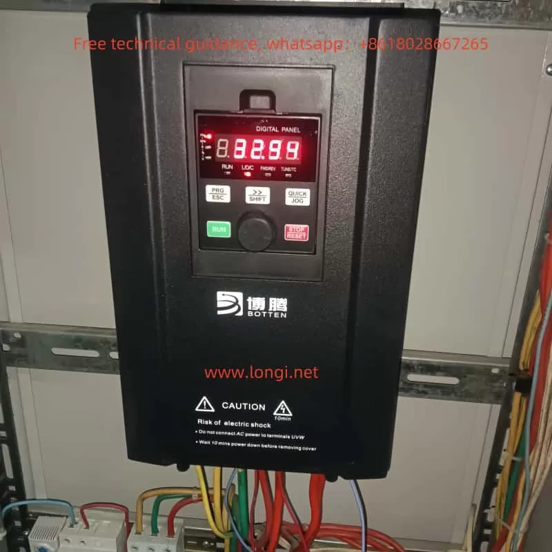
1. Operation Panel Functions
The operation panel of the Boteng A558 series frequency inverter integrates multiple functions, allowing users to modify parameters, monitor status, and control operation through the panel. The main functions of the operation panel include:
- Program Key (PRG/ESC): Used to enter or exit menus and return to the previous menu.
- Confirmation Key (ENTER): Used to confirm parameter settings or enter the next menu level.
- Increment Key (+) and Decrement Key (-): Used to adjust data or function code values.
- Shift Key (>): Used to cycle through different parameters or select modification positions in the stop display interface and parameter modification interface.
- Run Key (RUN): Used to start the inverter.
- Stop/Reset Key (STOP/RESET): Used to stop the inverter or reset faults.
- Jog Key (QUICK/JOG): Used for jog operation or direction switching.
2. How to Copy Parameters to Another Inverter
To copy parameters from one inverter to another, follow these steps:
- On the source inverter, enter the parameter setting menu and select the “Parameter Backup” function.
- Export the parameters to a USB drive or other storage device.
- On the target inverter, insert the storage device, enter the parameter setting menu, and select the “Parameter Restore” function.
- Import the parameters from the storage device to complete the copying process.
3. How to Set and Remove Passwords
Setting a password can prevent unauthorized operations. The specific steps are as follows:
- Enter the parameter setting menu and find the password setting option (usually P7-49).
- Enter a new password (range: 0~65535) and confirm to save.
- To remove the password, set it to the default value of 0.
4. How to Set Parameter Access Restrictions
To prevent misoperation, you can set parameter access restrictions:
- Enter the parameter setting menu and find the parameter access restriction option.
- Set the parameter access permissions, such as allowing only specific users to modify critical parameters.
- Save the settings to ensure the parameter access restrictions take effect.
5. Setting the Rated Frequency, Voltage-to-Frequency Ratio, and Acceleration/Deceleration Time
For a machine tool-specific inverter, setting the rated frequency and voltage-to-frequency ratio is crucial. The specific steps are as follows:
- Rated Frequency Setting: In parameter P0-14, set the maximum frequency of the inverter (usually the rated frequency of the motor, such as 50Hz or 60Hz).
- Voltage-to-Frequency Ratio Setting: In parameter P2-01, set the torque boost value (usually 0%~30%) to ensure the inverter provides sufficient torque at low frequencies.
- Acceleration/Deceleration Time Setting: In parameters P0-23 and P0-24, set the acceleration and deceleration times, respectively, in seconds (s), with a range of 0.0~30000.0s.
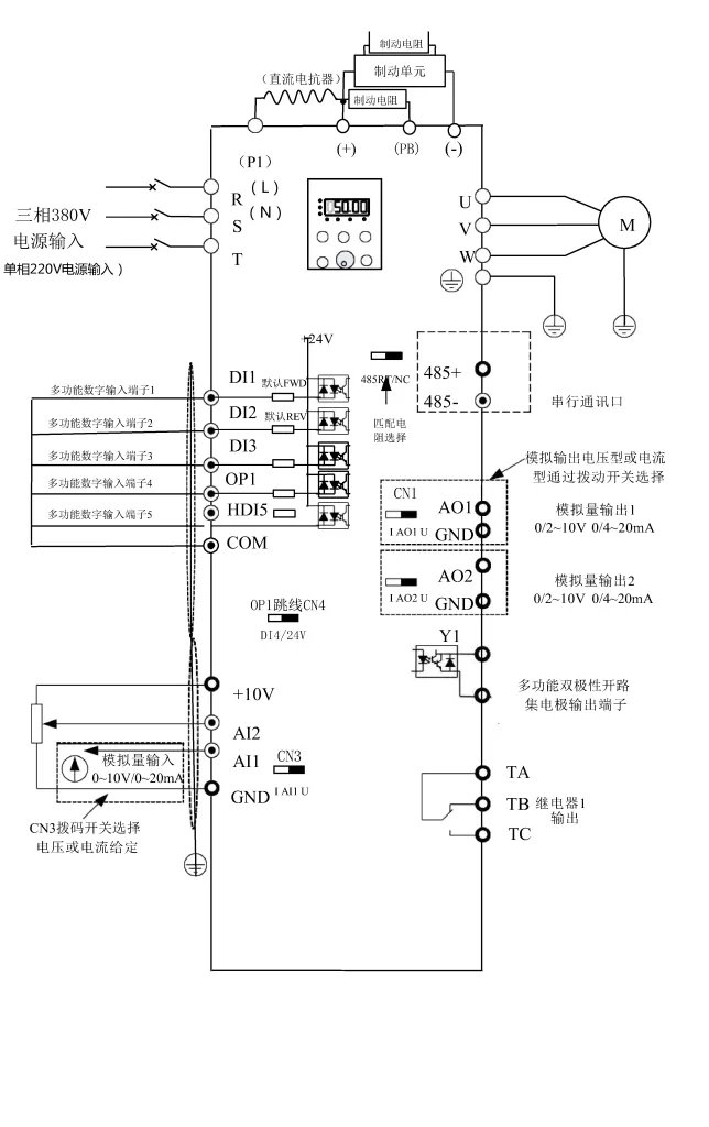
II. External Terminal Control and Speed Adjustment
1. External Terminal Forward/Reverse Control
To achieve external terminal control of the inverter’s forward and reverse operation, you need to set the following parameters:
- Terminal Function Setting: In parameters P5-00 and P5-01, set the functions of terminals D11 and D12, respectively. For example, set D11 to forward operation (FWD) and D12 to reverse operation (REV).
- Wiring: Connect the external control signals to terminals D11 and D12. When D11 is connected, the inverter operates forward; when D12 is connected, the inverter operates in reverse.
2. External Potentiometer Speed Adjustment
To achieve speed adjustment through an external potentiometer, you need to set the following parameters:
- Potentiometer Input Setting: In parameter P0-06, select the potentiometer as the frequency source (e.g., select AI1 or AI2).
- Potentiometer Range Setting: In parameters P5-22 and P5-23, set the input range of the potentiometer and the corresponding frequency values.
- Wiring: Connect the potentiometer output to the analog input terminal of the inverter (A11 or A12) to adjust the output frequency of the inverter through the potentiometer.
III. Fault Codes and Troubleshooting
1. Common Fault Codes
The Boteng A558 series inverter may encounter various faults during operation. Common fault codes and their meanings are as follows:
- Err01: Inverter module protection, possible causes include motor short circuit, module overheating, etc.
- Err04: Overcurrent during acceleration, possible causes include incorrect motor parameters, short acceleration time, etc.
- Err15: Drive overheating, possible causes include high ambient temperature, fan failure, etc.
- Err23: Input phase loss, possible causes include power supply faults or wiring issues.
2. Troubleshooting Methods
For different fault codes, the following troubleshooting methods can be adopted:
- Err01: Check if the motor and wiring are normal, and replace the inverter module if necessary.
- Err04: Check the motor parameter settings and appropriately extend the acceleration time.
- Err15: Lower the ambient temperature and check if the fan is working properly.
- Err23: Check the power supply and wiring to ensure normal power supply.
IV. Conclusion
The Boteng A558 series frequency inverter is a powerful inverter designed specifically for machine tools. By reasonably setting parameters and operating correctly, precise control of machine tools can be achieved. This article provides a detailed introduction to the operation panel functions, parameter settings, and troubleshooting of the inverter, aiming to provide valuable reference for users. During use, if problems are encountered, it is recommended to refer to the user manual or contact the manufacturer for technical support to ensure the normal operation of the equipment.