Delta VFD MS300 Series User Guide
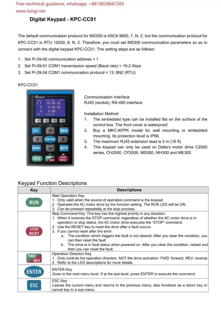
I. Operating Panel Usage
- Power-On and Display
- Upon powering on, the VFD automatically conducts a self-test and then enters standby mode. The display on the operating panel shows the current status and parameters.
- Function Key Operations
- RUN/STOP Button: Press RUN to start the VFD and STOP to halt its operation.
- Direction Selection (FWD/REV): Used to select forward or reverse rotation for the motor.
- Frequency Adjustment Keys: Adjust the output frequency using the up and down arrow keys. In automatic mode, these keys may be disabled.
- MENU Button: Enters the main menu, allowing access and modification of various settings.
- ENTER Button: Confirms the current selection or enters setup mode.
- ESC Button: Exits the current setup or returns to the previous menu level.
- Parameter Settings
- Navigate to the parameter settings menu, use the arrow keys to select the parameter to modify, press ENTER to enter edit mode, adjust the parameter value with the up/down arrow keys, and confirm with ENTER.

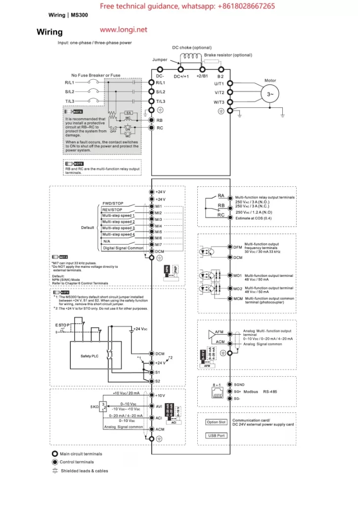
II. Wiring for Terminal Start and Potentiometer Speed Control
- Starting Terminal Wiring
- Forward Start (FWD): Connect the external control signal to the VFD’s forward start terminal (e.g., FWD).
- Reverse Start (REV): For reverse rotation, connect the signal to the reverse start terminal (e.g., REV). Typically, forward and reverse cannot be activated simultaneously.
- Stop: Connect the stop signal to the VFD’s stop terminal to interrupt output.
- Potentiometer Speed Control Wiring
- Connect a potentiometer to the analog input terminal (e.g., AVI or ACI) of the VFD. Attach the two fixed ends of the potentiometer to the VFD’s power supply (e.g., +10V and GND), and connect the sliding end to the VFD’s analog input terminal.
- According to the parameter settings in the manual (e.g., parameter 03-00), configure the relevant parameter to “frequency command” so that the VFD can adjust its output frequency based on the voltage signal from the potentiometer.

III. Parameter Configuration
- Basic Parameter Settings
- Maximum Operating Frequency (Parameter 01-00): Set the maximum output frequency based on the motor specifications.
- Acceleration/Deceleration Time (Parameters 01-12 through 01-19): Configure appropriate acceleration and deceleration times to avoid mechanical shocks and overcurrents, tailored to your application’s needs.
- Starting Frequency (Parameter 01-09): Set the initial frequency at startup to mitigate starting surges.
- Input/Output Terminal Configuration
- Multi-function Input Terminals (Parameters 02-01 through 02-07): Assign each terminal’s function according to your control requirements, such as start, stop, and direction control.
- Analog Input Configuration (e.g., Parameter 03-00): Specify the function of AVI, ACI, and other analog input terminals, such as frequency reference or torque control.
- Protection Parameters
- Overcurrent Protection (Parameters 06-03 through 06-04): Configure the overcurrent protection threshold and duration to safeguard the motor and VFD.
- Overvoltage/Undervoltage Protection (Parameters 06-00, 06-01): Set voltage protection thresholds to ensure stable operation amidst voltage fluctuations.
IV. Fault Code Analysis and Resolution
- Overcurrent (OC)
- Cause: Excessive motor load, too short acceleration time, motor malfunction, etc.
- Resolution: Inspect the motor and load conditions, adjust the acceleration time, and check for motor damage.
- Overvoltage (OV)
- Cause: Excessive input voltage, too short deceleration time, insufficient braking resistance, etc.
- Resolution: Verify the input voltage, adjust the deceleration time, and consider adding braking resistance.
- Undervoltage (LV)
- Cause: Low input voltage, voltage drop due to long power lines, etc.
- Resolution: Check the power supply voltage and optimize power line layout.
- Overheating (OH)
- Cause: High ambient temperature, poor heat dissipation, excessive load, etc.
- Resolution: Improve cooling conditions, reduce the load, and inspect and clean the cooling fan.
- Communication Fault
- Cause: Communication line issues, incorrect parameter settings, address conflicts, etc.
- Resolution: Examine the communication lines, verify communication parameter settings, and ensure unique device addresses.
By following this guide, you can effectively use and maintain the Delta VFD MS300 series, ensuring stable operation and optimal performance.
