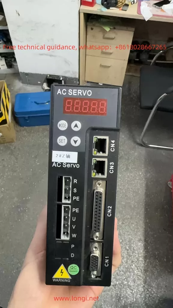
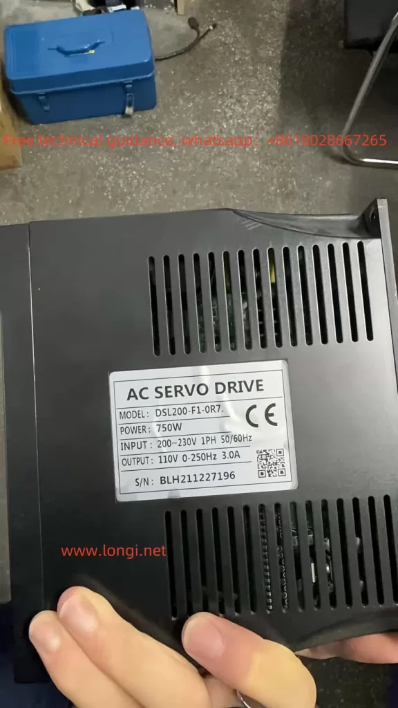
The DPK Servo DSL200-F1 is a high-performance servo drive widely used in industrial automation. This article provides a detailed introduction to its operation panel functions, monitoring status, jog operation and test run methods, homing settings, wiring and parameter configuration for position and speed modes, and analysis and solutions for common fault codes to help users operate this device efficiently.
1. Operation Panel Functions and Monitoring Status
The operation panel of the DSL200-F1 includes the following main functions:
- Display Screen: Used to display running status, parameter settings, and fault codes.
- Function Keys: For switching menus, confirming settings, or returning to the previous menu.
- Rotary Encoder: For quickly adjusting parameter values.
- Indicator Lights: Show the servo status (e.g., running, alarm, etc.).

The monitoring status function helps users check key parameters of the servo in real time, including:
- Monitoring Status Parameters:
Fn-17: Input status terminal (displays the status of input terminals, address 4×1297).Fn-18: Output terminal status (displays the status of output terminals, address 4×1298).Fn-19: Encoder value input signal (address 4×1299).Fn-20: Servo running status, displayed as “Rn On” to indicate running (address 4×1300).Fn-21: Alarm codes, e.g., “ALE 9” indicates alarm 9 (address 4×1301).Fn-22: External speed analog voltage input value (e.g., U 0.000V, address 4×1302).Fn-23: External torque analog voltage input value (e.g., U 0.000V, address 4×1303).Fn-24: Servo alarm count memory, e.g., AC 8 indicates 8 alarms (address 4×1304).
2. Parameter Table Overview

Below is an explanation of some important parameters:
1. Monitoring Parameters:
P0-00: Software version, factory default is 407 (address 4×0000).P0-01: Hardware version, factory default is 200 (address 4×0001).P0-02: Parameter default value recovery.- Set to 0: No operation.
- Set to 1: Restore to factory default parameters.
- Set to 2: Absolute encoder motor zero point position setting (manufacturer use).
- Default value is 0, address 4×0002.
P0-03: Software reset.- Set to 0: No operation.
- Set to 1: Servo software reset.
- Default value is 0, address 4×0003.
P0-04toP0-08: Record the last five alarm codes, default value is 0, addresses 4×0004 to 4×0008.
2. Expansion Parameters:
P1-00: Control mode selection.- Range: 0~100.
- Default value: 0, address 4×0256.
- Refer to section 4.6 for control mode definitions.
P1-01: Pulse command direction and encoder feedback direction setting.- Range: 0~3.
- Default value: 0, address 4×0257.
P1-02: External pulse train command input form setting.- Range: 0~7.
- Default value: 0, address 4×0258.
- 0: Pulse + direction, 4: CCW/CW pulse, 6: A/B phase pulse.
P1-03: Control command input source setting.- Range: 0~2.
- Default value: 0, address 4×0259.
- 0: Control command from terminal.
- 1: Control command via ModBus RTU (RS-485).
- 2: Control command via CAN communication.
P1-04: Internal servo start setting.- Range: 0~1.
- Default value: 0, address 4×0260.
- 0: Servo disabled.
- 1: Servo enabled.
- After setting parameters, press and hold the “SET” key for 3 seconds to save.
P1-05: Motor model code.- Range: 0~100.
- Default value: 2, address 4×0261.
- When
P0-02=1, the servo automatically restores parameters to factory defaults based on the motor model code. P1-06: Electronic gear numerator (N).- Range: 1~32767.
- Default value: 1, address 4×0262.
P1-10: Electronic gear denominator (M).- Range: 1~32767.
- Default value: 1, address 4×0266.

[Further parameter descriptions omitted for brevity in this draft.]
3. Implementing JOG Operation and Test Run
1. JOG Operation:
The JOG operation is used to check the motor rotation direction or make fine adjustments. Steps are as follows:
- Set
P1-00=12to let the servo enter JOG mode. - Set
P1-04=1to enable the servo. - Enter parameter
P4-00and assign a speed command. - Press the start button on the panel and use the direction keys to select the rotation direction.
- Release the start button to stop the jog operation.
2. Test Run:
Test runs verify the correctness of the connection between the servo drive and motor.
- Enable test run mode in the menu (
P4-60). - Set the running speed (
P3-01) and running time (P3-02). - Press the start button to begin the test, observing whether the motor runs smoothly.
- Press the stop button to complete the test.
4. Homing Methods and Settings
The DSL200-F1 supports the following homing methods:
1. Limit Switch + Z Pulse Homing:
- Set
P1-28=1and connect the limit switch to the ORG1 input terminal. - The motor will search for the limit switch position at high speed (
P1-30) and then search for the Z pulse signal at low speed (P1-31). - A completion signal is output after homing.
2. Z Pulse + Offset Homing:
- Set
P1-28=2, and the offset is determined by parametersP1-32andP1-33. - The motor searches for the Z pulse at low speed and then stops based on the set offset.
3. DOG Detection Homing:
- Set
P1-28=3. The servo motor stops upon detecting the DOG signal.
5. Position and Speed Mode Wiring and Parameter Settings
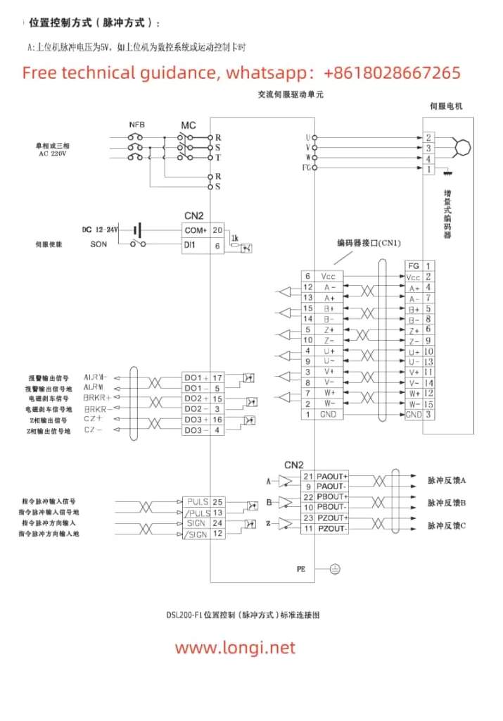
1. Position Mode Control:
Position mode is used for precise control of motor position.
- Wiring: Connect the controller’s pulse + direction signal to the servo drive’s
PULSEandSIGNterminals. - Parameter Settings:
- Set the pulse equivalent (
P2-02). - Set acceleration and deceleration time (
P2-26, default is 100ms). - Activate position control mode (
P1-00=pt).
- Testing: Verify proper position control using external pulse signals.
2. Speed Mode Control:
Speed mode is used to control motor speed.
- Wiring: Connect the analog speed signal (-10V to +10V) to the
V-REFterminal. - Parameter Settings:
- Set speed gain (
P2-18). - Adjust the low-pass filter (
P2-21). - Activate speed control mode (
P1-00=st).
- Testing: Input different voltage signals and observe the motor speed response.
6. Fault Code Analysis and Solutions
Common fault codes for DSL200-F1 include:
1. ALE 01: Overspeed Alarm
- Cause: Command frequency too high or encoder fault.
- Solution:
- Check whether the pulse input frequency exceeds the limit.
- Replace the encoder or inspect encoder wiring.
2. ALE 02: Main Circuit Overvoltage
- Cause: Abnormal braking circuit or excessive power supply voltage.
- Solution:
- Check whether the braking resistor connection is normal.
- Add an external braking resistor.
3. ALE 05: Motor Overheating
- Cause: Excessive motor load or poor ventilation.
- Solution:
- Check ambient temperature and load conditions.
- Reduce the load or add cooling devices.
4. ALE 10: Control Power Undervoltage
- Cause: Insufficient control power input.
- Solution:
- Check the control power voltage.
- Ensure firm wiring connections.
7. Summary
The DPK Servo DSL200-F1 provides rich functionality and flexible control modes. By proper operation and settings, it can meet diverse industrial application requirements. This article introduces the operation panel functions, JOG operation and test run, homing settings, position and speed mode control, and common fault solutions in detail. For further information, refer to the official manual or contact technical support.
