I. Display Menu and Status Monitoring
1.1 Operation and Settings of the Display Menu

The GSK DAP03 spindle drive unit is equipped with a 6-digit LED digital tube for displaying various statuses and parameters. Users can operate the display menu and monitor statuses through the following steps:
Status Monitoring: Users can press corresponding buttons to select different monitoring statuses. For example, pressing the “+” or “-” button can flip through different monitoring contents such as motor speed, current position, input/output terminal status, etc. The specific monitoring content can be selected by setting parameter PA3, and the content displayed after power-on can also be set according to this parameter.
Parameter Setting: In parameter setting mode, users can adjust parameter values using the “+” and “-” buttons, and save the settings by pressing the “Confirm” button. Note that after modifying certain key parameters, a parameter write operation (EE-SEt) is required to ensure the changes take effect.
1.2 Settings for Status Monitoring
Status monitoring allows users to view various statuses of the drive unit in real-time, such as motor speed, position, alarm codes, etc. Users can select the specific monitoring content by setting parameter PA3. For example, setting PA3 to “0” will display motor speed by default after power-on; setting it to “1” will monitor the low five-digit pulse count of the current motor position, and so on.
II. Manual and Inching Control
2.1 Manual Control
In manual control mode, users can directly control the motor’s forward and reverse rotation as well as acceleration and deceleration using the “+” and “-” buttons on the operation panel. The specific steps are as follows:
- Set PA4=2 to select manual operation mode.
- Set PA33=1 to enable forced enable (not dependent on external enable signals).
- Enter the manual operation menu and control the motor using the “+” and “-” buttons. Pressing the “+” button accelerates the motor, pressing the “-” button decelerates it, and releasing the buttons allows the motor to maintain its current speed.
2.2 Inching Control
Inching control allows users to briefly run the motor at a preset speed. The specific steps are as follows:
- Set PA4=3 to select inching operation mode.
- Set PA21 to the desired inching speed (e.g., 300 represents 300 RPM).
- Set PA33=1 to enable forced enable.
- Enter the inching operation menu and press the “+” or “-” button to start the motor in forward or reverse rotation. The motor stops when the button is released.

III. Position and Speed Control Modes
3.1 Position Control Mode
In position control mode, users control the motor’s precise position through pulse commands. The specific wiring and parameter settings are as follows:
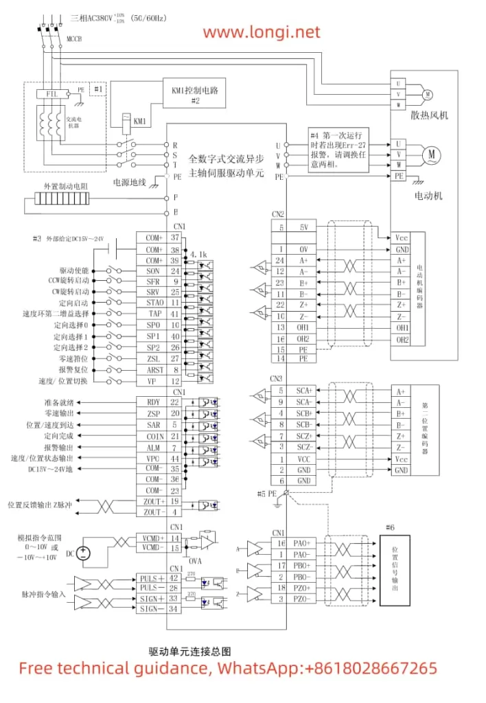
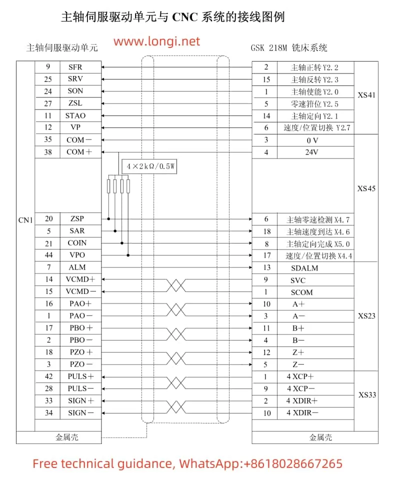
Wiring: Connect the PULS+, PULS-, SIGN+, SIGN- terminals of the CN1 interface to receive position commands.
Parameter Settings:
- Set PA4=0 to select position mode.
- Set PA12 (position pulse command multiplication factor) and PA13 (position pulse command division factor) as needed to calculate the electronic gear ratio.
- Set PA14 to select the pulse command mode (e.g., pulse + direction).
3.2 Speed Control Mode
In speed control mode, users can control the motor’s speed through analog voltage commands or internal digital commands. The specific wiring and parameter settings are as follows:
Analog Voltage Command Control:
- Wiring: Connect the VCMD+, VCMD- terminals of the CN1 interface to receive analog voltage commands.
- Parameter Settings: Set PA4=1 and PA22=1 to select analog command speed mode, and set PA42 to the motor speed corresponding to 10V analog input.
Internal Digital Command Control:
- Wiring: Connect the SP0, SP1, SP2, etc., terminals of the CN1 interface to select preset speeds.
- Parameter Settings: Set PA4=1 and PA22=0 to select internal command speed mode, and set the speeds for each segment through PA24 to PA30.
3.3 Electronic Gear Ratio Setting
The electronic gear ratio is used to convert input commands into the motor’s actual movement. The calculation formula is:
G = (ZM × CD × δ × CR × PA13) / (PA12 × ZM × L)
Where ZM and ZD are the gear ratios at the screw end and motor end (both are 1 when directly connected), L is the screw lead, C is the motor encoder’s number of lines, δ is the system’s minimum output command unit, and CR and CD are the multiplication and division factors for the upper machine’s commands. Users need to set PA12 and PA13 according to the actual mechanical structure to achieve the desired electronic gear ratio.
IV. Common Alarm Codes and Troubleshooting
The GSK DAP03 spindle drive unit displays corresponding alarm codes when abnormalities are detected. Below are some common alarm codes, their meanings, and troubleshooting methods:
- Err-1: The spindle motor speed exceeds the set value. Possible causes include abnormal encoder feedback signals, improper acceleration/deceleration time settings, etc. Troubleshooting methods include checking encoder connections, adjusting acceleration/deceleration time parameters, etc.
- Err-5: Motor overtemperature alarm. Possible causes include no temperature detection device inside the motor, overload, etc. Troubleshooting methods include setting PA73=1 to disable the alarm, reducing the load, etc.
- Err-9: Abnormal motor encoder signal feedback. Possible causes include poor encoder signal wire connections, damaged encoders, etc. Troubleshooting methods include checking encoder connections, replacing encoders, etc.

V. Err-11 Alarm Code Meaning and Troubleshooting
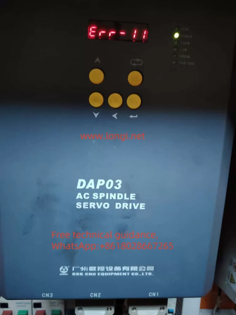
The Err-11 alarm code indicates a fault in the intelligent power module (IPM) inside the drive unit. The IPM is a core component of the drive unit, responsible for converting DC power into AC power to drive the motor. When the IPM detects abnormalities or damage, it triggers the Err-11 alarm.
Possible Causes:
- IPM Overheating: Long-term high-load operation or poor heat dissipation may cause the IPM to overheat, leading to failure.
- Short Circuit or Overload: Short circuits in the motor or power lines, as well as motor overload operation, can damage the IPM.
- Power Voltage Fluctuations: Unstable power voltage may cause abnormal IPM operation or even damage.
- IPM Quality Issues: In rare cases, the IPM may have manufacturing defects or early failure.
Troubleshooting Methods:
- Check Power Voltage: Ensure stable input power voltage that meets the drive unit’s voltage requirements. If the power voltage fluctuates significantly, consider installing a voltage stabilizer.
- Check Motor and Wiring: Disconnect the motor from the drive unit and check for short circuits or grounding faults in the motor and wiring. Use tools such as a multimeter to perform resistance and insulation tests to ensure the wiring is intact.
- Improve Heat Dissipation: Ensure the drive unit’s cooling fan is working properly and the heatsink is clean of dust. In high-temperature or harsh environments, consider adding additional cooling measures, such as installing fans or lowering the ambient temperature.
- Replace the IPM: If the above steps fail to solve the problem, it may be due to IPM failure. In this case, contact the supplier or manufacturer to purchase and replace the IPM. When replacing, ensure power is off, and the new module is compatible with the old one.
- Contact Technical Support: If the problem persists, it is recommended to contact GSK’s technical support team for assistance. They can provide more professional fault diagnosis and repair advice.
Notes:
- When dealing with any faults related to electrical equipment, always cut off the power first to ensure personal safety.
- If you do not have relevant professional knowledge and skills, do not attempt to repair the drive unit or IPM yourself. Incorrect operations may lead to further equipment damage or safety hazards.
By following the above steps, you should be able to diagnose and solve the Err-11 alarm issue in the GSK DAP03 spindle drive unit. If the problem persists, seek help from professional technicians.
