I. Introduction to the Operation Panel Functionality and Password, Function Code Settings

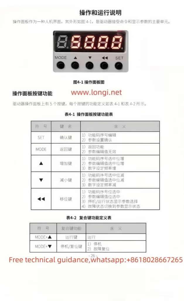
The operation panel of the GTAKE GS100M spindle drive serves as the primary interface for user interaction. The panel comprises five buttons: SET (confirm), MODE (return), ▲ (increase), ▼ (decrease), and ◀◀ (shift). These buttons enable users to configure drive functions and adjust parameters.
Password Function Setup and Removal
To protect the drive from unauthorized modifications, the GS100M offers a password protection feature. Users can set a password by configuring function code A0-00. To remove the password, restore the value of A0-00 to the default 0000.
Function Code Display and Protection Settings
Function code A0-01 controls the display range of function codes. Users can select to display all function codes, only certain function codes, or only those with values different from the factory defaults. Additionally, function code A0-02 provides function code protection; when set to 1, only A0-00 and this function code can be modified, locking other function codes to prevent accidental changes.
Function Code Initialization and Backup Settings
To restore the drive to factory settings, users can configure function code A0-03. Selecting different values can clear fault records, restore all parameters to factory defaults (with or without motor parameters), or backup the current parameters to function codes. Backup parameters can be achieved by setting function code A0-04 for quick restoration when needed.
II. Parameter Settings for Controlling Synchronous Motors
To control synchronous motors, users must correctly set a series of parameters. First, select the motor type as synchronous via function code d0-00. Then, configure the synchronous motor’s basic parameters such as rated power (d0-01), rated voltage (d0-02), and rated current (d0-03). Next, set the electrical parameters including stator resistance (d0-15), direct-axis inductance (d0-16), quadrature-axis inductance (d0-17), and back EMF constant (d0-18). Additionally, set the motor’s identification current (d0-19) and initial angle (d0-20). After completing the parameter settings, perform motor parameter identification (d0-22) to ensure accuracy.

III. Pulse Input + Direction Input Frequency Setting and External Terminal Startup Configuration
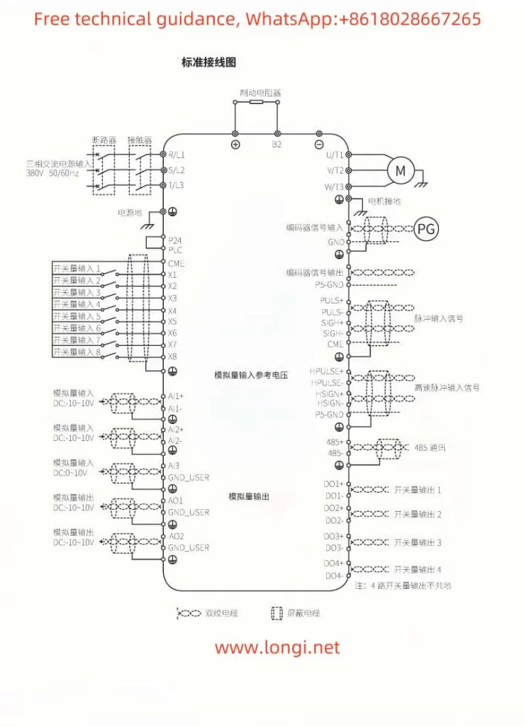
To use pulse input + direction input for frequency setting and external terminal startup, users need to correctly wire the terminals and configure the relevant parameters.
Wiring Instructions
- Pulse Input (PULS+ and PULS-): Connect the positive and negative terminals of the pulse signal to the drive’s PULS+ and PULS- terminals, respectively.
- Direction Input (SIGN+ and SIGN-): Connect the positive and negative terminals of the direction signal to the drive’s SIGN+ and SIGN- terminals, respectively.
- External Start Terminal: Depending on specific requirements, connect the external start signal to the corresponding multi-function input terminal, such as X1, X2, etc.
Parameter Settings
- Function Code C0-22: Set to 2 to select pulse train position control pulse input mode.
- Function Code b0-01: Set to 5 or 11 to choose the frequency setting method based on the pulse input channel.
- Function Code b1-00: Set to 1 to select terminal control mode, enabling startup via external terminals.
- Multi-function Terminal Settings: Use function codes C0-01 to C0-08 to configure the corresponding multi-function terminals for pulse input, direction input, and external startup functions.
IV. Fault Code Meaning Analysis and Resolution Methods
The GS100M drive provides detailed fault codes to help users quickly locate and resolve issues. Below are some common fault codes, their meanings, and resolution methods:
- oC1 (Acceleration Overcurrent): Excessive current during acceleration. Possible causes include excessive torque boost, high starting frequency, and short acceleration time. Resolution methods include reducing torque boost, lowering the starting frequency, and extending the acceleration time.
- oL2 (Motor Overload): Excessive motor load. Possible causes include heavy loads and improper motor parameter settings. Resolution methods include reducing the load and correctly setting parameters according to the motor nameplate.
- ov1 (Acceleration Overvoltage): High voltage during acceleration. Possible causes include abnormal input voltage and large load inertia. Resolution methods include checking the grid voltage and using dynamic braking.
- CtC (Current Detection Circuit Anomaly): Fault in the current detection circuit. Possible causes include abnormal control board and drive board connections and damaged current sensors. Resolution methods include checking and reinserting the cable and seeking service.
By carefully reading and understanding the user guide section of the GS100M manual, users can better master the drive’s operation, parameter settings, and fault handling methods, ensuring smooth and efficient drive operation.
