
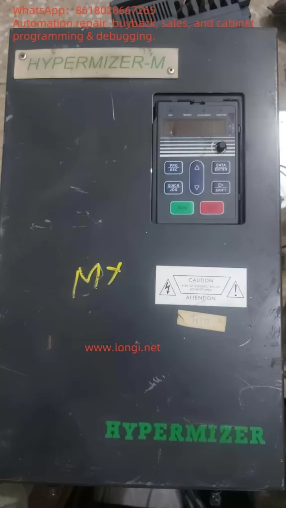
Introduction to the Operation Panel
The operation panel of the HYPERMIZER-M RT4 series inverter provides various functions for parameter settings, status monitoring, and operational control. Below is an overview of the main functions of the operation panel:
Function Indicator Lights
- RUN: Indicates the running status. The light is off when the inverter is stopped and on when it is running.
- FWD/REV: Indicates forward or reverse operation. The light is off for forward operation and on for reverse operation.
- LOCAL/REMOT: Indicates the control mode. The light is off for keypad control, on for terminal control, and flashing for remote communication control.
- TUNE/TRIP: Indicates overload warning. The light is on for torque control mode, flashes slowly during self-learning, and flashes quickly during a fault.
Unit Indicator Lights
- Hz: Frequency unit.
- A: Current unit.
- V: Voltage unit.
- RPM: Speed unit.
- %: Percentage.
Display Area
The 5-digit LED display shows the set frequency, output frequency, and other monitoring data, as well as alarm codes.
Keypad Buttons
- PRG/ESC: Program key for entering or exiting the first-level menu.
- DATA/ENTER: Confirmation key for entering the next menu level and confirming parameter settings.
- △: Increment key for increasing data or function codes.
- ▽: Decrement key for decreasing data or function codes.
- □: Shift key for cycling through display parameters in stop or run mode and selecting the modification position for parameters.
- RUN: Run key for starting operation in keypad mode.
- STOP/RST: Stop/Reset key for stopping operation or resetting from a fault.
- QUICK/JOG: Multifunction key for switching functions based on P7-01 settings.
Setting and Removing Passwords
Setting a Password
- Enter the function parameter mode and locate PP-00 (User Password).
- Set a non-zero value as the user password.
- Exit the function parameter mode; the password protection will be activated.
Removing a Password
- Enter the function parameter mode and input the correct user password.
- Locate PP-00 (User Password) and set it to 0.
- Exit the function parameter mode; the password protection will be deactivated.
Setting Parameter Access Restrictions
- Enter the function parameter mode and locate PP-04 (Function Code Modification Attribute).
- Set to 0 for modifiable or 1 for non-modifiable.
Restoring Factory Default Settings
- Enter the function parameter mode and locate PP-01 (Parameter Initialization).
- Set to 01 to restore default values, excluding motor parameters.
- Set to 02 to clear recorded information.
Forward/Reverse Control via Terminals and External Potentiometer Speed Control
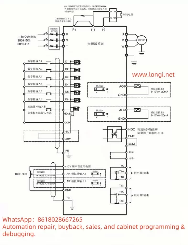
Forward/Reverse Control via Terminals
- Terminals: FWD (Forward), REV (Reverse).
- Parameter Settings: Set P4-00 (D1 Terminal Function Selection) to 1 (Forward Operation) or 2 (Reverse Operation).
External Potentiometer Speed Control
- Terminals: AI1 (Analog Input Terminal 1).
- Parameter Settings: Set P0-03 (Main Frequency Source A Selection) to 4 (Panel Potentiometer Setting).
Fault Codes and Handling
Fault Codes
- 01: Overcurrent fault.
- 02: Undervoltage fault.
- 03: Overvoltage fault.
- 04: Overheating fault.
- 05: Phase loss fault.
- 06: Overload fault.
- 07: Short circuit fault.
- 08: Communication fault.
- 09: Encoder fault.
- 10: Parameter read/write fault.
Fault Handling
- Overcurrent Fault: Check if the motor and load are normal; ensure the motor is not overloaded.
- Undervoltage Fault: Check if the input voltage is normal; ensure the voltage is within the allowed range.
- Overvoltage Fault: Check if the input voltage is too high; ensure the voltage is within the allowed range.
- Overheating Fault: Check if the inverter’s cooling is normal; ensure the cooling fan is working properly.
- Phase Loss Fault: Check if the input power supply has a phase loss; ensure the power supply is normal.
- Overload Fault: Check if the motor and load are overloaded; ensure the load is within the allowed range.
- Short Circuit Fault: Check if the motor and load are short-circuited; ensure the circuit is normal.
- Communication Fault: Check if the communication lines are normal; ensure the communication equipment is working properly.
- Encoder Fault: Check if the encoder is working properly; ensure the encoder signal is normal.
- Parameter Read/Write Fault: Check if the parameter settings are correct; ensure the parameters are within the allowed range.
Conclusion
The user manual for the HYPERMIZER-M RT4 series inverter provides detailed operational guidance and fault handling methods, helping users correctly operate and maintain the inverter. By understanding the operation panel functions, setting passwords and parameter access restrictions, restoring factory default settings, implementing forward/reverse control via terminals, and external potentiometer speed control, as well as identifying and handling common faults, users can better utilize the inverter’s capabilities, improving work efficiency and extending the equipment’s lifespan.