
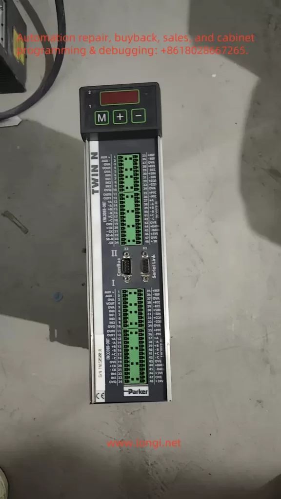
The Parker servo system TWIN-N/SPD-N series is a high-performance servo drive system widely used in industrial automation, robotics, and precision control applications. This guide provides detailed instructions on how to perform jog testing, position mode control, electronic cam functionality, and troubleshooting for this system.
1. Jog Testing
Jog testing is a crucial step in the calibration and verification of servo systems. Here’s a detailed guide on how to perform jog testing:
Wiring Steps:
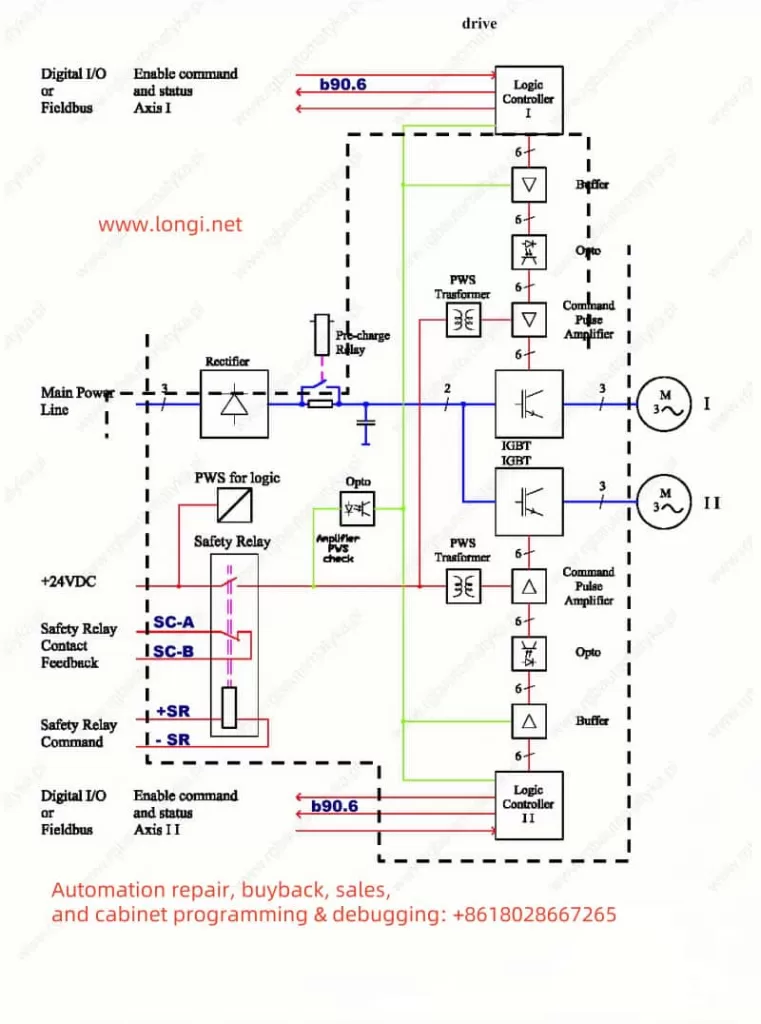
- Power Connection: Connect the three-phase power supply lines L1, L2, and L3 to the drive’s terminals 1, 2, and 3, respectively. For single-phase or DC power supply, refer to the user manual for the appropriate wiring diagram.
- Motor Connection: Connect the motor’s U, V, and W phases to the drive’s terminals 5, 6, and 7 (Motor I). For dual-axis drives (TWIN-N), connect the second motor’s U, V, and W phases to terminals 9, 10, and 11 (Motor II).
- Encoder Connection (if used): For incremental encoders, connect the A+, A-, B+, and B- signal lines to terminals 13, 14, 15, and 16, respectively. For sine/cosine encoders, connect the Sin+, Sin-, Cos+, and Cos- signal lines to terminals 6, 7, 8, and 9, respectively.
- Control Signal Connection: Connect the 24V control power supply to terminals 24 and 48. Connect the analog reference input to terminals 1 and 2 (Rif. AUX + and Rif. AUX -). Connect the JOG operation buttons to digital input terminals (e.g., IN0, IN1) for start, stop, and direction control.
Parameter Settings:
- Initialize Parameters: After powering on, set the drive to default parameters using the keypad. Set
b99.7andb99.13to 0, issue commandb99.12, and save the settings (b99.14andb99.15). - Set Motor Parameters: Input motor parameters such as pole count (Pr29), rated speed (Pr32), rated current (Pr33), encoder pole count (Pr34), motor impedance (Pr46), and inductance (Pr47).
- Set Feedback Type: Configure feedback parameters based on the encoder type (e.g.,
b42.9,b42.8,b42.7,b42.6). - Adjust Speed Loop Parameters: Set the integral gain (Pr16) and damping (Pr17) of the speed loop, adjusting based on system response.
- Set Acceleration/Deceleration Time: Configure acceleration and deceleration times (Pr8, Pr9, Pr10, Pr11).
- Set Limiting Parameters: Set overspeed limit (Pr13), high-speed limit (Pr14), low-speed limit (Pr15), and peak current (Pr19).
Jog Operation Procedure:
- After powering on, start the JOG operation by pressing the corresponding buttons. One button can start the motor in the forward direction, and another can start it in reverse.
- Releasing the button should stop the motor immediately or according to the set deceleration.
Open-Loop Mode Testing:
In open-loop mode (without an encoder), the drive operates the motor using V/F control by varying the frequency of the input voltage. Set the motor type to asynchronous (Pr217 = 1) and input related parameters such as base speed (Pr218), slip (Pr219), and magnetizing current (Pr220). In this mode, the drive estimates the motor’s speed and position by detecting the back EMF.
2. Position Mode Forward and Reverse Control
Position mode control is commonly used in servo systems to precisely control the motor’s position. Here’s how to implement forward and reverse control in position mode:
Wiring Steps:
- In addition to the power and motor connections, connect a position feedback device (e.g., an encoder) to the drive’s corresponding terminals.
Parameter Settings:
- Set Position Mode: Select the position mode in the operation settings (e.g.,
Pr31 = 13or14). - Set Position Parameters: Configure target position (e.g., Pr62:63), speed (Pr8, Pr9), and acceleration (Pr10, Pr11).
- Enable Position Control: Ensure the position feedback device is correctly connected and calibrated.
Forward and Reverse Control:
Control the motor’s forward and reverse rotation by setting the target position to positive or negative values. For example, a positive target position will rotate the motor forward, while a negative value will rotate it in reverse.
3. Electronic Cam Functionality
The electronic cam function is an advanced feature of servo systems used for complex motion control. Here’s how to implement it:
Implementation Steps:
- Set Electronic Cam Parameters: Select the electronic cam mode in the operation settings (e.g.,
Pr31 = 14). Configure the cam table parameters, such as position, speed, and acceleration. - Configure Cam Table: Set up the data points in the cam table according to the motion requirements.
Using CAN Protocol:
- CAN Wiring: Connect the CAN communication lines to the drive’s CAN interface terminals.
- Set CAN Parameters: Configure the CAN communication speed (e.g., Pr48) and CANopen address (e.g., Pr49).
- Configure CAN Communication: Set up the data frames and control words for CAN communication according to the user manual.
4. Troubleshooting Fault Codes
Servo systems may encounter various faults during operation. Understanding fault codes and how to handle them is crucial for maintaining system stability. Here are common fault codes and their handling methods:
- Overcurrent Fault (Pr23 = 1): Check the motor and cable connections, and ensure the load is within rated limits.
- Overvoltage Fault (Pr23 = 2): Verify the power supply voltage and ensure it is stable.
- Overheating Fault (Pr23 = 3): Check the drive and motor cooling, and ensure proper ventilation.
- Encoder Fault (Pr23 = 4): Inspect the encoder connections and signals, and ensure the encoder is functioning correctly.
Handling Procedure:
- Identify the fault code and refer to the user manual for the fault description.
- Inspect the relevant components and connections based on the fault description.
- After resolving the fault, restart the system and monitor its operation.
Conclusion
The Parker servo system TWIN-N/SPD-N series is a powerful and versatile servo drive system. By following the correct wiring and parameter settings, users can perform jog testing, position mode control, and electronic cam functionality. Understanding fault codes and their handling methods ensures the system’s stable operation. This guide provides comprehensive instructions to help users effectively utilize this servo system, enhancing work efficiency and control precision.