
Introduction
The Pioneer VF2100 series frequency converter plays a crucial role in the field of industrial control, widely used in speed control for various mechanical equipment. To ensure the stable operation and efficient use of the frequency converter, it is essential to master its usage methods and troubleshoot common issues. This article will provide a comprehensive guide to the operation panel functions, parameter copying and settings, terminal control, fault code handling, and the meaning of the U-10 display for the Pioneer VF2100 series frequency converter.
I. Operation Panel Function Introduction
The operation panel of the Pioneer VF2100 series frequency converter integrates various functions to facilitate parameter setting and status monitoring.
- Digital Operator: Used to set frequency commands and operation commands, while displaying various parameters and statuses. The LED indicators (such as SEQ, REF, RUN, STOP, etc.) on the digital operator can visually indicate the current operation mode and status.
- Key Functions:
- LOCAL/REMOTE Key: Switches between local and remote operation modes. In local mode, users can directly control the frequency converter through the operation panel; in remote mode, the frequency converter accepts operation commands from external control signals.
- DSPL Key: Switches between monitoring items, allowing users to view different parameters and status information.
- ENTER Key: Confirms the set value. When users modify parameters or set frequencies, pressing this key saves the changes and exits the setting interface.
Additionally, the operation panel typically includes keys such as STOP (to stop operation), RUN (to start operation), and UP/DOWN (for parameter adjustment), which collectively form the frequency converter’s operation control system.
II. Parameter Copying and Settings
- Parameter Copying:
The Pioneer VF2100 series frequency converter supports parameter copying, although specific copying steps are not directly mentioned in the manual. However, through communication interfaces such as MEMOBUS, users can send and receive data, including parameter setting and reading. This means that, although not explicitly stated in the manual, users may indirectly achieve parameter copying through communication interfaces.In practical operation, parameter copying may involve the following steps: First, select the parameters to be copied on the source frequency converter; then, send these parameters to the target frequency converter through the communication interface; finally, receive and save these parameters on the target frequency converter. - Password and Parameter Access Restriction Settings:
To protect the frequency converter parameters from unauthorized modification, the Pioneer VF2100 series provides password protection. Users can set passwords and control access permissions by setting parameter n001.- Password Levels:
- 0: Allows reading/setting of n001 and reading of n002-n108.
- 1: Allows reading/setting of n001-n034 and reading of the second function reference group (n035-n049) and the third function (n050-n108).
- 2: Allows reading/setting of the first and second functions and reading of the third function.
- 3: Allows reading/setting of all functions.
- Password Levels:
- Parameter Initialization:
When frequency converter parameters become disorganized or need to be reset to factory settings, users can perform parameter initialization. Specifically, set parameter n001 to 6 (for 2-wire initialization) or 7 (for 3-wire initialization), then follow the prompts to complete the parameter initialization.
III. Terminal Forward/Reverse Control and External Potentiometer Speed Regulation
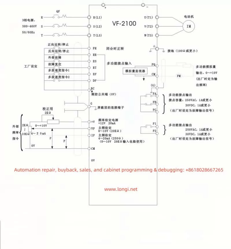
- Terminal Forward/Reverse Control:
The Pioneer VF2100 series frequency converter supports motor forward/reverse control through control terminals. Specific wiring and settings are as follows:- Forward Operation: Close the contact between control circuit terminals FR and BC to control the motor to operate forward.
- Reverse Operation: Close the contact between control circuit terminals RR and BC to control the motor to operate in reverse.
- Disable Reverse Operation: Set parameter n006 to 1 to disable the reverse operation command.
- External Potentiometer Speed Regulation:
The Pioneer VF2100 series frequency converter also supports frequency command input through an external potentiometer, enabling motor speed control. Specific settings and wiring are as follows:- Set Parameters: Set parameter n042 to 0 to select the main frequency command as the voltage signal (0-10V) of the control circuit terminal VF.
- Wiring: Connect the output of the external potentiometer to the VF terminal. Adjusting the resistance of the potentiometer changes the voltage signal on the VF terminal, thereby changing the frequency command of the frequency converter and achieving motor speed control.
IV. Fault Code Explanation and Handling
The Pioneer VF2100 series frequency converter may encounter various faults during operation, which are typically indicated by fault codes. Users need to be familiar with these fault codes and their meanings to promptly take measures for fault handling.
The manual provides a detailed fault code table (Table 15), listing various fault codes, descriptions, details, and countermeasures. For example, fault code Uu1 indicates insufficient main circuit voltage, and the countermeasure is to check the power wiring and correct the incoming voltage. When the frequency converter displays a fault code, users should follow the guidance in the manual to troubleshoot and handle the fault to ensure the normal operation of the frequency converter.
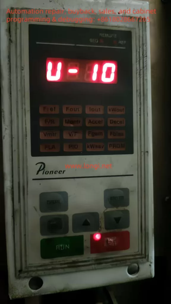
V. Meaning of U-10 Display
When using the Pioneer VF2100 series frequency converter, users may encounter the display of U-10. So, what does U-10 mean? Is it a fault code?
In fact, U-10 in the Pioneer VF2100 series frequency converter is not a fault code but a display for monitoring the low 4 digits of the PROM (Programmable Read-Only Memory) number. This means that when the frequency converter displays U-10, users can view the firmware version or specific configuration information of the frequency converter through it.
Therefore, when the frequency converter displays U-10, users do not need to worry about faults but should regard it as an information prompt. If users need to confirm the firmware version or configuration information of the frequency converter, they can obtain relevant information by observing the U-10 display.
VI. Conclusion
Through this article, we have gained a detailed understanding of the operation panel functions, parameter copying and settings, terminal control, fault code handling, and the meaning of the U-10 display of the Pioneer VF2100 series frequency converter. These knowledge and skills are crucial for ensuring the stable operation and efficient use of the frequency converter.
In practical applications, users should master the operation methods of the frequency converter and closely monitor its operating status and fault codes. When encountering faults, users should promptly troubleshoot and handle them to ensure the continuous operation of the production line. At the same time, users should make full use of the various functions and parameter settings of the frequency converter to meet different production needs and control requirements.
Finally, it is essential to emphasize the importance of correctly handling the U-10 display to ensure the normal operation of the frequency converter. Users should regard it as an information prompt rather than a fault code and take corresponding actions and handling measures based on actual situations.
I hope this translated article meets your needs. If you have any further questions or require additional assistance, please feel free to ask.