I. Introduction to Operation Panel Functions
1. Panel Display Settings
On the operation panel of the SAJ PDG10 series inverter, you can view the current actual pressure and frequency in real-time. To set the panel to display the current actual pressure and frequency, you can use the “SHIFT” button to cycle through the display options. In the running state, pressing the “SHIFT” button allows you to toggle between running frequency, output current, set pressure, and feedback pressure.

2. Leakage Coefficient Function and Adjustment
The leakage coefficient (F0.04) is used to adjust issues where the inverter fails to enter sleep mode due to pipeline leakage. When there is leakage in the pipeline, the inverter may not enter sleep mode due to continuous minimal flow. At this point, the leakage coefficient can be adjusted to optimize the sleep function. The greater the leakage, the smaller this coefficient should be set. The default value is 5.0 seconds, with an adjustable range of 0.0 to 100.0 seconds and a minimum adjustment unit of 0.1 seconds.
3. Anti-Freezing and Rust-Proof Function and Settings
The anti-freezing and rust-proof function (F0.03) is used to protect the water pump from damage caused by low temperatures. When this function is enabled, the inverter automatically adjusts the water pump’s operating frequency based on the set parameters to prevent damage from low temperatures. This function has two setting options: timing by seconds or minutes. Simultaneously, the anti-freezing operating frequency (F0.12), anti-freezing operating time (F0.13), and anti-freezing operation interval (F0.14) need to be set.
4. Sensor Channel Selection and Range Setting
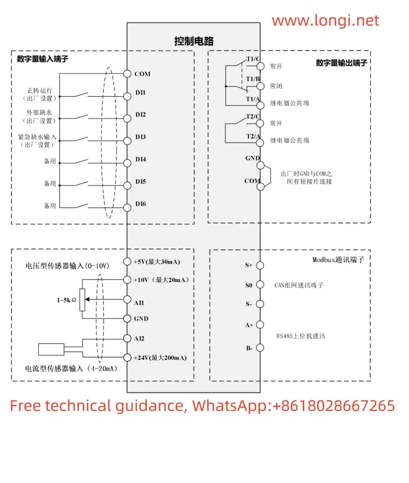
The inverter supports two analog input channels (AI1 and AI2) for receiving pressure sensor signals. The sensor channel (AI1, AI2, or the maximum/minimum value between them) can be selected through parameter F0.09. At the same time, parameter F0.08 needs to be set according to the actual pressure sensor range used to ensure that the inverter can correctly interpret sensor signals.
II. Single Pump Control Wiring and Parameter Settings
1. Wiring Instructions
In single pump control scenarios, the inverter wiring is relatively simple. Primarily, the power supply needs to be connected to the R, S, T three-phase power input terminals, the motor to the U, V, W output terminals, and the grounding terminal should be reliably grounded. If external control signals (such as start/stop, fault reset, etc.) are required, the corresponding control wires should be connected to DI1, DI2, and other digital input terminals.
2. Parameter Setting Steps
- Step 1: Set the sensor range (F0.08) and feedback channel (F0.09).
- Step 2: Set the pipe network pressure (F0.00) according to actual needs.
- Step 3: Choose the start mode (F0.05), such as keyboard start, terminal start, or communication control start.
- Step 4: Set the feedback type for AI1 or AI2 channels (F2.00 or F2.02) based on the sensor type.
- Step 5: If necessary, further adjust parameters such as acceleration time (F0.18) and deceleration time (F0.19) to optimize water pump performance.

III. Realization of One-to-Two Timed Alternating Control
1. Wiring Instructions
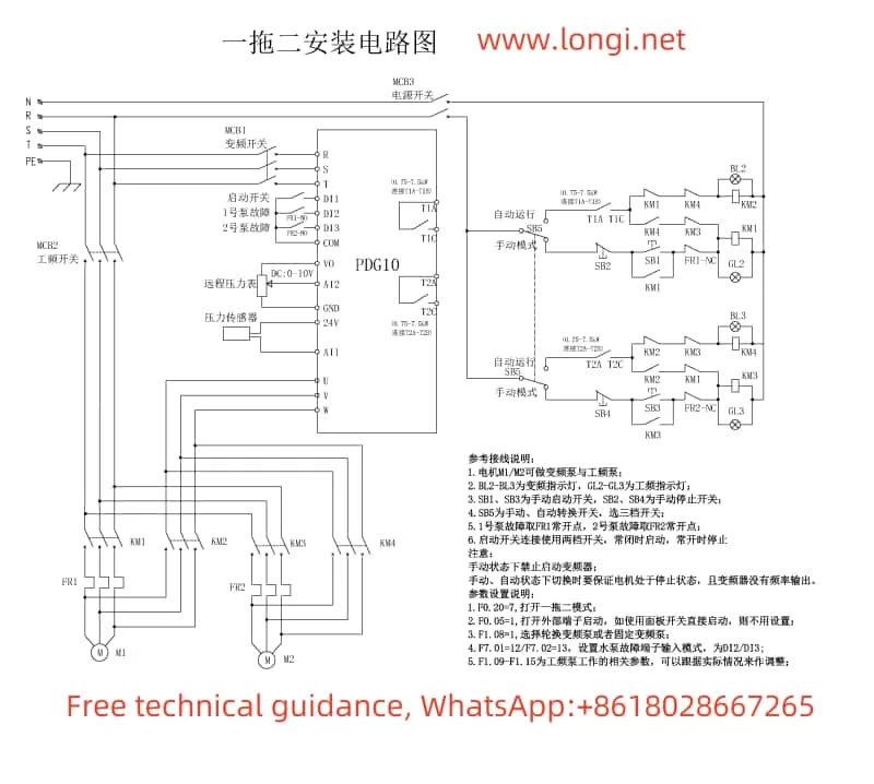
In one-to-two timed alternating control, an additional power-frequency pump and its control circuit need to be connected. The primary wiring includes connecting the inverter’s output terminals U, V, W to the variable-frequency pump motor, the power-frequency power supply to the power-frequency pump motor, and using contactors and relays to control the circuit to realize the switching between the variable-frequency pump and the power-frequency pump. The specific wiring diagram can be found on page 68 of the manual.
2. Parameter Settings
- F0.20: Set to 7 to enable one-to-two mode.
- F1.08: Set to 1 to select alternating variable-frequency pump mode.
- F0.05: Set to 1 to enable terminal start mode (if communication control start is required, set to 2).
- F1.09-F1.15: Set parameters such as pump-on pressure deviation, pump-on delay time, pump-off pressure deviation, and pump-off delay time according to actual needs.
- F3.12 and F3.13: Set the sleep holding frequency and sleep detection frequency to optimize sleep performance.
3. Control Logic
When the pipe network pressure drops below the set value, the inverter first starts the variable-frequency pump and accelerates it. When the variable-frequency pump operates at the upper limit frequency but still cannot meet the pressure demand, it automatically switches to the power-frequency pump. After the set alternation time, the system switches back to the variable-frequency pump, realizing timed alternation control between the two pumps.
IV. Conclusion
The SAJ PDG10 series inverter provides rich functions and flexible parameter setting options to meet the needs of different application scenarios. Through this guide, you can quickly understand the functions of the operation panel, the setting methods for the leakage coefficient and anti-freezing function, the selection and range setting of sensor channels, the wiring and parameter setting steps for single pump control, and the realization of one-to-two timed alternating control. We hope this content will help you better utilize the SAJ PDG10 series inverter products.
