I. Introduction to User Panel Functions and Settings

1. Access Privileges and User Password Settings
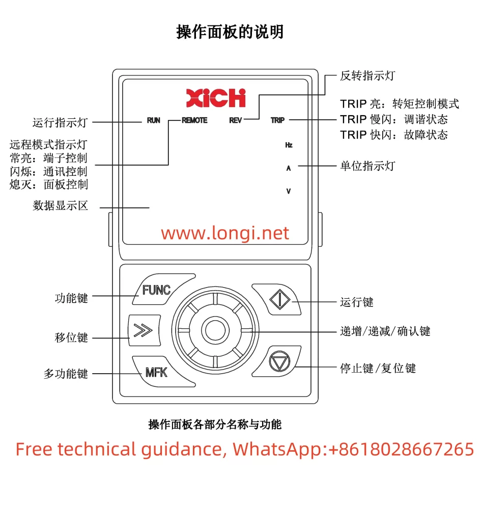
The Xichi Inverter XFC500 series offers different levels of access privileges to protect user parameters from unauthorized modification. Through the operation panel, users can enter the parameter setting menu and select the “b0-03” function code to set the parameter modification attribute. Options include “0: Modifiable” and “1: Not Modifiable”. Additionally, users can set a user password by configuring the “b0-05” function code to protect parameters from being modified by unauthorized personnel. To clear the password, simply set “b0-05” to “0”.
2. Parameter Initialization
When users need to restore factory settings, they can achieve this by setting the “b0-01” function code. Options include “0: No Operation”, “1: Restore Factory Parameters (excluding motor parameters and GP type settings)”, and “2: Clear Record Information”. Selecting “1” will restore the inverter to its factory default settings, but motor parameters and GP type settings will remain unchanged.
3. PWM-related Parameter Settings
PWM (Pulse Width Modulation) parameters significantly impact the operating performance of the inverter. Users can adjust the carrier frequency by setting the “C0-03” function code, with a range of 0.5kHz to 16.0kHz. A lower carrier frequency may increase motor noise and current harmonics, while a higher carrier frequency may increase inverter losses and temperature rise. Furthermore, the “C0-04” function code allows users to enable automatic carrier frequency adjustment based on temperature to avoid overheating.
II. Realization of Terminal Forward/Reverse and External Potentiometer Speed Regulation
1. Terminal Forward/Reverse Function
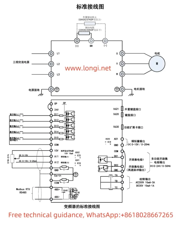
To achieve the forward/reverse function of the inverter, users need to correctly set the multifunction digital input terminals. Typically, forward rotation can be set by configuring the “F1-00” function code to “1: Forward Run (FWD)”, and reverse rotation to “2: Reverse Run (REV)”. During wiring, connect the forward control signal to the corresponding digital input terminal (e.g., DI1) and the reverse control signal to another digital input terminal (e.g., DI2).
2. External Potentiometer Speed Regulation
External potentiometer speed regulation is usually achieved through analog input terminals. Users can select “F0-01” function code to set the main frequency source to “AI1” (Analog Input 1). During wiring, connect the sliding contact of the external potentiometer to the AI1 terminal, and the fixed contacts to the GND terminal of AI1 and the common terminal of the inverter (e.g., COM terminal). Additionally, the input curve of AI1 needs to be set through function codes such as “F1-25” to “F1-28” to determine the correspondence between the potentiometer position and the output frequency.

III. Fault Code Meaning Analysis and Solutions
1. Err09: Undervoltage Fault
When the inverter detects that the input voltage is below the set value, it will report an Err09 fault. Solutions include checking whether the input power supply is normal, whether the voltage is stable, and whether the cable connections are reliable.
2. Err11: Motor Overload
The Err11 fault typically indicates that the motor is overloaded. Users should check whether the motor is operating under overload conditions, whether the load exceeds the motor’s rated capacity, and whether there is any jamming in the transmission mechanism.
3. Err15: External Fault
The Err15 fault indicates that the external fault input terminal has been activated. Users should check whether the external fault signal source is normal and whether the wiring is reliable. If the external fault signal is a false operation, the relevant circuits and components should be checked.
IV. Conclusion
The XFC500 Series Manual of Xichi Inverter provides users with detailed operation instructions and parameter setting methods. By reasonably setting access privileges and user passwords, users can protect inverter parameters from unauthorized modification. By correctly setting PWM parameters, terminal forward/reverse, and external potentiometer speed regulation functions, users can achieve precise control over the inverter. Additionally, the manual provides detailed analysis and solutions for fault codes, helping users quickly locate and resolve issues. Overall, the manual is well-structured, logically clear, and an essential reference for users to operate and maintain the inverter.
