
I. Introduction to the Operation Panel Functions and Basic Settings of the Inverter
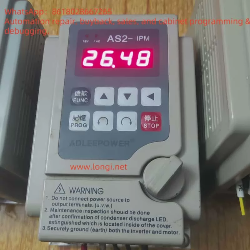
The ADLEEPOWER AS series inverter is a high-performance, multifunctional inverter with an intuitive operation panel and rich features. The operation panel mainly includes the following function keys:
- FWD/RUN: Forward run key. Pressing this key will rotate the motor in the forward direction.
- REV/RUN: Reverse run key. Pressing this key will rotate the motor in the reverse direction.
- SHIFT: Shift key. Used to switch the position of digits during parameter setting.
- UP/DOWN: Up/down keys. Used to increase or decrease values during parameter setting.
- PROG: Memory key. Used to save the currently set parameters.
- FUNC: Function key. Used to select the function to be set.
- STOP: Stop key. Pressing this key will stop the motor and return it to standby mode.
Restoring Factory Default Parameters
To restore the inverter’s parameters to factory defaults, follow these steps:
- Press the PROG key to enter parameter setting mode.
- Use the UP/DOWN keys to find the CD52 parameter (regional version).
- Press the FUNC key to enter parameter modification mode.
- Use the UP/DOWN keys to set the CD52 parameter to USA (for the US version) or Eur (for the European version), then press the PROG key to save.
- Power off and restart the inverter. The parameters will be restored to factory defaults.
Setting and Removing Passwords
The AS series inverter supports password protection to prevent unauthorized parameter modifications. To set a password, follow these steps:
(Note: The specific password setting method may vary depending on the model. The following are general steps.)
- Enter parameter setting mode.
- Find the parameter related to password setting (refer to the user manual of the specific model for the exact parameter number).
- Use the UP/DOWN keys to set the password, then press the PROG key to save.
To remove the password, simply set the password parameter to the default value or leave it blank.
Setting Parameter Access Restrictions
The AS series inverter also supports parameter access restriction functions, which can limit users’ access and modification permissions for certain parameters. To set parameter access restrictions, follow these steps:
- Enter parameter setting mode.
- Find the parameter related to parameter access restrictions (refer to the user manual of the specific model for the exact parameter number).
- Use the UP/DOWN keys to set the access level, then press the PROG key to save.
II. Terminal Forward/Reverse Control and External Potentiometer Frequency Setting for Speed Regulation
Terminal Forward/Reverse Control
The AS series inverter supports forward/reverse control of the motor through external terminals. The specific wiring and parameter settings are as follows:
- Wiring:
- Connect the forward control signal terminal of the external control signal to the FWD terminal of the inverter.
- Connect the reverse control signal terminal of the external control signal to the REV terminal of the inverter.
- Ensure that the common terminal of the external control signal is connected to the COM terminal of the inverter.
- Parameter Settings:
- Enter parameter setting mode.
- Find the CD12 parameter (terminal or keyboard selection).
- Set the CD12 parameter to 1, indicating that the forward/reverse control of the motor is through the terminals.
External Potentiometer Frequency Setting for Speed Regulation
The AS series inverter also supports speed regulation by setting the frequency through an external potentiometer. The specific wiring and parameter settings are as follows:
- Wiring:
- Connect the signal output terminal of the external potentiometer to the FA1 or FA2 terminal of the inverter (the specific terminal to be used depends on the parameter setting).
- Ensure that the common terminal of the external potentiometer is connected to the GND terminal of the inverter.
- Parameter Settings:
- Enter parameter setting mode.
- Find the CD10 parameter (analog or digital setting).
- Set the CD10 parameter to 1, indicating that the frequency is set through an analog signal (i.e., an external potentiometer).
- Set the CD44 or CD45 parameter (multi-function analog FA1 or FA2 setting) as needed to select the FA1 or FA2 terminal as the frequency setting input terminal.
III. DC BR Fault Analysis and Solution
Meaning of DC BR Fault
When the AS series inverter displays a “DC BR” fault, it usually indicates a DC braking fault. DC braking is a function of the inverter that injects DC current into the motor during shutdown to quickly decelerate or stop the motor. If there is a problem with the DC braking circuit, it may cause a “DC BR” fault.
Possible Causes of the Fault
- Damage to the DC Braking Resistor: The DC braking resistor is an important component in the DC braking circuit. If the resistor is damaged or aged, it may cause abnormal braking current, triggering the fault.
- Failure of the Braking Transistor: The braking transistor is responsible for controlling the on/off of the DC braking current. If the transistor is damaged or its performance degrades, it may also cause a braking fault.
- Improper Parameter Settings: If the parameters related to DC braking (such as braking time, braking current, etc.) are set improperly, it may result in poor braking performance or trigger a fault.
Solutions
- Check the DC Braking Resistor: Use a multimeter or other tools to check the resistance value of the DC braking resistor. If the resistor is damaged or aged, replace it with a new one.
- Check the Braking Transistor: Use a multimeter or other tools to check the performance of the braking transistor. If the transistor is damaged or its performance degrades, replace it with a new one.
- Check Parameter Settings: Recheck whether the parameters related to DC braking are set correctly. Adjust the parameter values according to the actual situation of the motor and braking requirements.
- Contact Technical Support: If the above methods cannot solve the problem, it is recommended to contact the technical support team or professional maintenance personnel of ADLEEPOWER inverters for further inspection and repair.
IV. Conclusion
The ADLEEPOWER AS series inverter, as a high-performance, multifunctional inverter product, has been widely used in the field of industrial automation. Through the introduction in this guide, users can better understand the operation panel functions, basic setting methods, terminal control and external speed regulation functions, as well as fault solution methods of the inverter. It is hoped that this guide can provide help and guidance to users when using the AS series inverters.