The Bosch Rexroth VFC3610/VFC5610 series frequency converters are high-performance devices widely used in industrial automation, mechanical processing, pump and fan control, and other fields. This article provides a detailed guide on using the user manual for these frequency converters, including operating panel functions, parameter settings, and troubleshooting.

I. Operating Panel Function Introduction
1.1 Operating Panel Functions
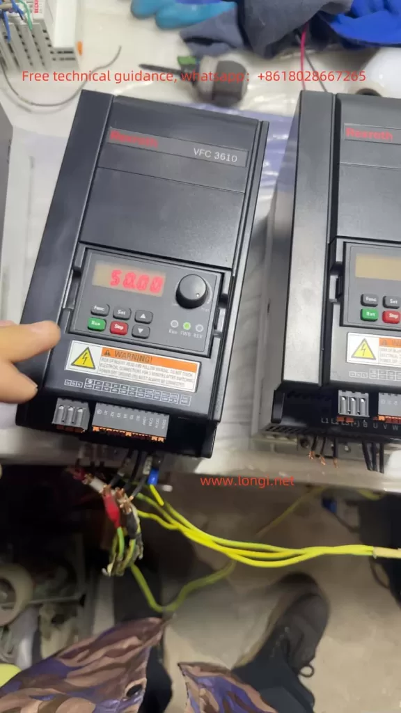
The operating panel of the Bosch Rexroth VFC3610/VFC5610 series offers a range of functions for parameter settings, monitoring, and diagnostics. The main components include an LED display, navigation knob, function button, stop button, and run button.
- LED Display: Shows the operating status, parameter values, and fault codes.
- Navigation Knob: Used to select parameter groups/parameters and set parameter values.
- Function Button (Func): Enters the parameter group screen and returns to the previous screen.
- Stop Button (Stop): Stops the frequency converter.
- Run Button (Run): Starts the frequency converter.
1.2 Parameter Copying
Users can copy parameter settings from one frequency converter to another using the parameter copy function:
- Back up parameters to the operating panel: Set parameter [b0.11] = ‘1: Backup parameters to the operating panel’.
- Install the operating panel on the target frequency converter.
- Set parameter [b0.11] = ‘2: Copy parameters from the operating panel’ to complete the parameter copying process.
1.3 Password Setting and Removal
To protect parameter settings, users can set a password. The steps for setting and removing the password are as follows:
- Set Password: Set parameter [b0.20] to the desired user password (range: 0…65,535).
- Remove Password: Set parameter [b0.20] to 0.
1.4 Parameter Access Restriction
To prevent unauthorized access to parameter settings, the frequency converter offers access restriction features. Users can set parameter [b0.00] to limit access rights:
- 0: Basic parameters
- 1: Standard parameters
- 2: Advanced parameters
- 3: Startup parameters
- 4: Modified parameters
1.5 Parameter Initialization
In some cases, users may need to initialize the frequency converter parameters to their default settings. The steps are as follows:
- Set parameter [b0.10] = ‘1: Restore default settings’.
- The frequency converter will automatically revert to the factory default settings.

II. External Terminal Control and Speed Adjustment
2.1 External Terminal Forward and Reverse Control
Users can control the forward and reverse operations of the frequency converter through external terminals. The steps are as follows:
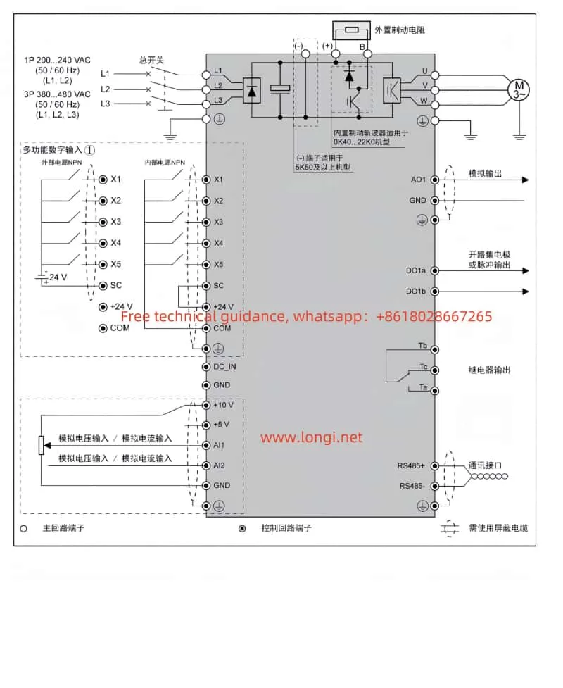
- Set parameter [E0.17] = ‘0: Forward / Reverse’.
- Connect the terminals:
- X1: Multifunctional digital input for forward control.
- X2: Multifunctional digital input for reverse control.
2.2 External Potentiometer Speed Adjustment
Users can adjust the speed of the frequency converter using an external potentiometer. The steps are as follows:
- Set parameter [E0.00] = ‘2: Al1 Analog Input’.
- Connect the terminals:
- Al1: Analog voltage input for frequency setting.
- GND: Common ground for analog input.
III. Fault Codes and Handling
3.1 Fault Codes
The Bosch Rexroth VFC3610/VFC5610 series provides detailed fault codes to help users quickly identify and resolve issues. Some common fault codes and their meanings are as follows:
- 0: No fault
- 1: OC-1, Overcurrent during constant speed
- 2: OC-2, Overcurrent during acceleration
- 3: OC-3, Overcurrent during deceleration
- 4: OE-1, Overvoltage during constant speed
- 5: OE-2, Overvoltage during acceleration
- 6: OE-3, Overvoltage during deceleration
- 7: OE-4, Overvoltage during stop
- 8: UE-1, Undervoltage during operation
- 9: SC, Current surge or short circuit
- 10: IPH.L, Input phase loss
- 11: OPH.L, Output phase loss
- 12: ESS-, Soft start fault
- 20: OL-1, Overload
- 21: OH, Overheating
- 23: FF, Fan failure
- 24: Pdr, No-load protection
- 25: Col:, Command value loss
3.2 Fault Handling
When a fault occurs, users should take appropriate actions based on the fault code’s meaning. For example:
- Overcurrent Faults (1, 2, 3): Check if the motor and load are functioning correctly. Ensure proper cable connections and adjust parameter settings if necessary.
- Overvoltage Faults (4, 5, 6, 7): Check if the power supply voltage is stable. Ensure proper cable connections and adjust parameter settings if necessary.
- Undervoltage Fault (8): Check if the power supply voltage is normal. Ensure proper cable connections.
- Short Circuit Fault (9): Check cable and terminal connections for short circuits.
- Phase Loss Faults (10, 11): Check cable and terminal connections for phase loss.
- Overload Fault (20): Check if the motor and load are functioning correctly. Ensure proper cable connections and adjust parameter settings if necessary.
- Overheating Fault (21): Check the cooling conditions of the frequency converter. Ensure the fan is working properly and clean the heat sink if necessary.
- Fan Failure (23): Check if the fan is working properly. Replace the fan if necessary.
- No-load Protection (24): Check if the motor is running correctly and ensure the load is normal.
- Command Value Loss (25): Check communication cables and terminals for proper connections. Ensure communication is functioning correctly.
Conclusion
The Bosch Rexroth VFC3610/VFC5610 series frequency converters are powerful and user-friendly devices suitable for various industrial control applications. This guide provides a comprehensive overview of the operating panel functions, parameter settings, and fault handling for these frequency converters. By following this guide, users can effectively operate and maintain these devices, enhancing productivity and reliability.
