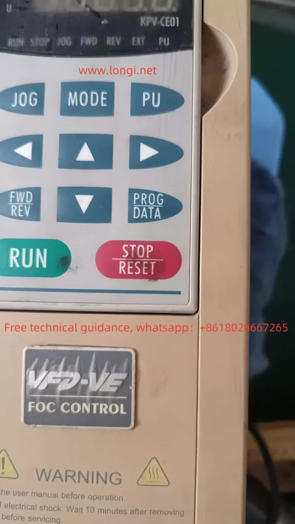
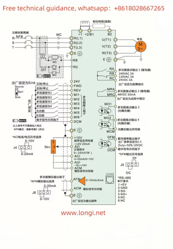
The Delta VFD-VE series is a high-performance variable frequency drive widely used in various industrial automation scenarios. This article provides a detailed guide on the operation panel functions, parameter settings, fault codes, and their solutions to help users effectively use and maintain this device.

Operation Panel Functions
Operation Panel Features
The operation panel of the Delta VFD-VE series is primarily composed of the digital operator KPV-CE01, which offers rich display and operation functions. Users can perform parameter settings, run control, and fault diagnosis through the panel. The main functions include:
- Parameter Settings: Users can set various parameters such as frequency, voltage, and current via the operation panel.
- Run Control: The panel provides basic run control functions such as start, stop, forward, and reverse.
- Fault Diagnosis: When a fault occurs, the panel displays the corresponding fault code to help users quickly identify and resolve issues.
Parameter Initialization
To restore the drive to its factory settings, follow these steps:
- Enter the parameter setting interface and locate parameter 00-02.
- Set parameter 00-02 to 9 (restore factory settings with a base frequency of 50Hz) or 10 (restore factory settings with a base frequency of 60Hz).
- Confirm the setting to reset all parameters to their default factory values.
Parameter Copying
To copy parameters from one drive to another, follow these steps:
- Use the parameter copy function of the digital operator KPV-CE01 to export and save the current drive’s parameters.
- Import the saved parameter file into the target drive to complete the parameter copying process.
Setting and Removing Passwords
To protect the drive’s parameter settings, users can set a password to restrict access:
- Enter the parameter setting interface and locate parameter 00-08.
- Input a 4-digit password. Once set, the parameters will be locked.
- To remove the password, set parameter 00-08 to 0.
Parameter Access Restriction
Users can restrict access to parameters by setting parameter 00-07:
- Enter the parameter setting interface and locate parameter 00-07.
- Input a 4-digit access code. Once set, only users who know the access code can modify the parameters.
External Terminal Control
Forward and Reverse Control via External Terminals
To implement forward and reverse control via external terminals, set the following parameters:
- Parameter 00-23: Set to 0 (forward and reverse allowed), 1 (reverse prohibited), or 2 (forward prohibited).
- Terminal Connections: Connect the external control signals to terminals FWD (forward) and REV (reverse).
Frequency Control via External Potentiometer
To achieve frequency control via an external potentiometer, set the following parameters:
- Parameter 00-20: Set to 2 (frequency controlled by external analog input).
- Terminal Connections: Connect the output signal of the external potentiometer to terminal AVI (analog voltage frequency command).
Fault Codes and Solutions
The Delta VFD-VE series may encounter various faults during operation. Here are some common fault codes and their solutions:
- OC (Overcurrent): Indicates that the drive has detected an overcurrent, possibly due to excessive load or motor failure. The solution is to check the load and motor status, reducing the load or replacing the motor if necessary.
- OV (Overvoltage): Indicates that the drive has detected an overvoltage, possibly due to a high source voltage. The solution is to check the source voltage and ensure it is within the allowable range.
- LV (Low Voltage): Indicates that the drive has detected a low voltage, possibly due to a low source voltage. The solution is to check the source voltage and ensure it is within the allowable range.
- OH (Overheat): Indicates that the drive is overheating, possibly due to poor heat dissipation or high ambient temperature. The solution is to check the heat dissipation conditions and ensure the drive is in a well-ventilated environment.
- PHL (Phase Loss): Indicates that the drive has detected a phase loss, possibly due to a fault in the power supply line. The solution is to check the power supply line and ensure it is functioning correctly.
- GFF (Ground Fault): Indicates that the drive has detected a ground fault, possibly due to an internal wiring fault. The solution is to check the internal wiring and replace any faulty components if necessary.

Conclusion
The Delta VFD-VE series is a powerful variable frequency drive that allows precise motor control through proper parameter settings and correct operation. This guide provides detailed information on the operation panel functions, parameter settings, fault codes, and their solutions to help users effectively use and maintain this device. In practical applications, users should set the drive’s parameters according to specific needs and environmental conditions to ensure stable and reliable operation.
