
Introduction
As a high-performance vector inverter, the Lingshida LSD-C7000 series is widely used in industrial drive applications. This guide aims to provide users with an in-depth understanding of the inverter’s operation panel functions, parameter settings, external control, and troubleshooting, ensuring efficient and safe operation of the equipment.
I. Operation Panel Functions and Key Parameter Settings
1.1 Introduction to Operation Panel Functions
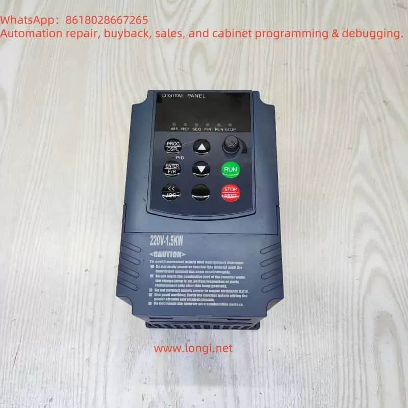
The LSD-C7000 series inverter’s operation panel integrates a variety of function keys and status indicators, including:
- Function Keys: RUN (run), STOP (stop), JOG (jog), PU/EXT (operation mode switch), SET (confirm), MODE (mode selection), etc.
- Status Indicators: RUN (green, running status), STOP (red, stop status), F/R (forward/reverse indication), ALARM (fault alarm), etc.
- Display Screen: Real-time display of set frequency, output current, voltage, power, speed, and other key parameters.
1.2 Factory Reset of Parameters
When needing to reset the inverter parameters, follow these steps:
- Enter programming mode: Press the MODE key to select parameter setting mode (usually displayed as “Pr” or “P”).
- Set the reset parameter: Enter
Pr001=11111(specific reset code) via the numeric keys. - Confirm execution: Press the SET key to confirm, and the inverter will automatically restart and restore all parameters to their factory defaults.
1.3 Password Setting and Access Restrictions
- Password Setting:
- Set a 4-digit password (range: 0-65535) via parameter
Pr800. - After setting, accessing protected parameters (such as Pr001-Pr800) requires entering the password.
- Set a 4-digit password (range: 0-65535) via parameter
- Password Elimination: Set
Pr800to0to remove password protection. - Access Restrictions: By setting
Pr800to an odd or even number, access permissions for different parameters can be controlled hierarchically.
II. External Terminal Control and Speed Regulation Configuration
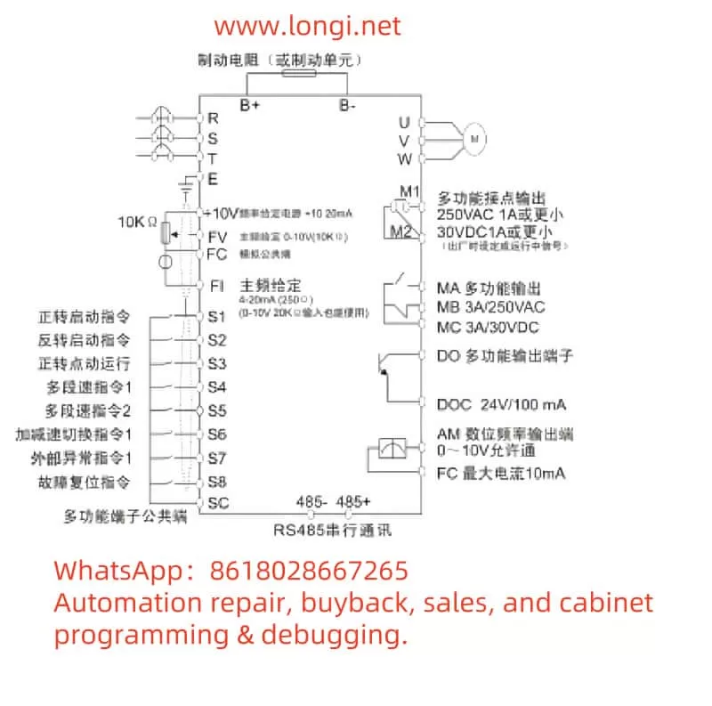
2.1 Forward/Reverse Control Wiring and Parameter Settings
- Wiring Method:
- Connect external switch or relay contacts to the inverter control terminals
S1(forward) andS2(reverse) respectively. - Ensure that the control circuit uses shielded wires to avoid electromagnetic interference.
- Connect external switch or relay contacts to the inverter control terminals
- Parameter Settings:
Pr006=1: Select terminal control mode.Pr301=1(forward function),Pr302=2(reverse function): Assign terminal control logic.
2.2 Potentiometer Speed Regulation Wiring and Parameter Settings
- Wiring Method:
- Connect the potentiometer output terminal to the inverter’s analog input terminal
FV, and connect it toGND. - It is recommended to use a 10kΩ linear potentiometer to obtain smooth speed regulation.
- Connect the potentiometer output terminal to the inverter’s analog input terminal
- Parameter Settings:
Pr004=1: Select analog input as the frequency command source.Pr203=100%(gain),Pr204=0%(offset): Calibrate the potentiometer output range.
III. Fault Code Analysis and Solutions
3.1 Common Fault Codes and Their Meanings
| Fault Code | Fault Name | Possible Causes |
|---|---|---|
| Uv1 | Undervoltage | Input voltage is below 70% of rated value |
| OC | Overcurrent | Motor overload, short circuit, or parameter setting error |
| OL1 | Motor Overload | Prolonged overload operation |
| SP | Input Phase Loss | Power supply phase loss or loose wiring |
| SPO | Output Phase Loss | Motor winding damage or poor contact |
3.2 Fault Handling Procedures
- Uv1/SP Handling:
- Check if the power supply voltage is within the rated range (e.g., 380V±15%).
- Ensure that the terminal connections are secure to avoid poor contact.
- OC/OL1 Handling:
- Reduce the load or adjust the acceleration time parameter (e.g.,
Pr005). - Check the motor insulation to rule out winding short circuits.
- Reduce the load or adjust the acceleration time parameter (e.g.,
- SPO Handling:
- Test the motor winding resistance and repair open or short circuits.
- Check the inverter output contactor contacts to ensure reliable conduction.
IV. Comprehensive Usage Suggestions
4.1 Regular Maintenance Items
- Clean the Heat Sink: Clean the heat sink dust quarterly to prevent overheating.
- Parameter Backup: Regularly back up parameter settings via the operation panel or dedicated software.
- Capacitor Inspection: Test the DC bus capacitor capacity every two years, and replace it if it is below 80%.
4.2 Safe Operation Practices
- Grounding Protection: Ensure reliable grounding of the inverter and motor, with a grounding resistance ≤4Ω.
- Prohibited Operations: Do not disconnect the control cable during operation to avoid signal interference causing misoperation.
- Environmental Adaptation: Avoid prolonged operation in environments with humidity >90% or temperature >45℃.
Through this guide, users can fully grasp the core operation and troubleshooting skills of the LSD-C7000 series inverter. It is recommended to combine the actual working conditions of the equipment and refer to the electrical schematic diagram in the manual for in-depth debugging to fully utilize the equipment’s performance. For complex faults, contact Lingshida’s technical support team promptly for professional guidance.