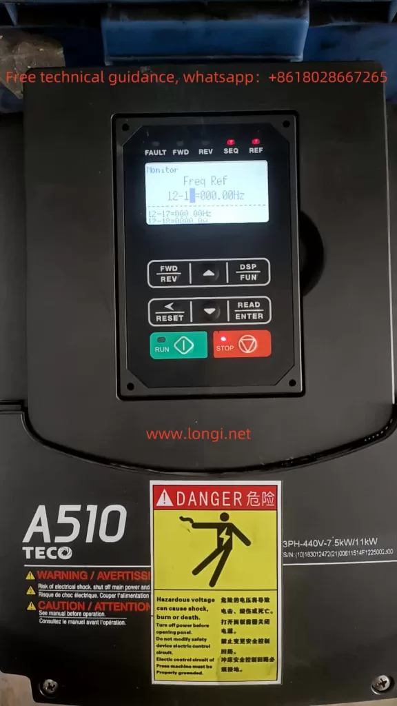
I. Introduction to the Operation Panel Functions and Settings for Passwords and Parameter Locks
The TECO A510S series frequency converter’s operation panel serves as its core control interface, offering intuitive operation and monitoring functions. Equipped with an LED display, multiple function keys, and status indicators, users can easily set parameters, monitor operating status, and troubleshoot faults.
Setting and Clearing Passwords:
To protect parameter settings from unauthorized changes, the A510S series provides a password protection feature. To set a password, users need to enter the “Maintenance Function Group” (parameter group 13) and set the “Parameter Password Function” (parameter 13-07) to a value between 0 and 65534. To clear the password, simply reset this parameter to 0.
Parameter Locking and Unlocking:
The parameter lock function prevents unauthorized users from modifying converter parameters. By setting “Parameter Lock” (parameter 13-06) to 1, users can restrict modifications to only preset “User Parameters” (parameters 00-41 to 00-56). To unlock all parameters, set this parameter to 2.
Setting Monitor Status to Current and Actual Frequency:
To monitor the converter’s current and actual output frequency in real-time, users need to enter the “Monitor Function Group” (parameter group 12) and adjust the “Display Screen Selection” (parameter 12-00) to set the LED display’s content. For example, setting the highest bit to 1 (output current) and the lowest bit to 2 (output voltage) will display both current and voltage on the panel. Similarly, by adjusting other bits of parameter 12-00, users can select other monitoring parameters like actual frequency.

II. Terminal Forward/Reverse Control and External Potentiometer Speed Regulation
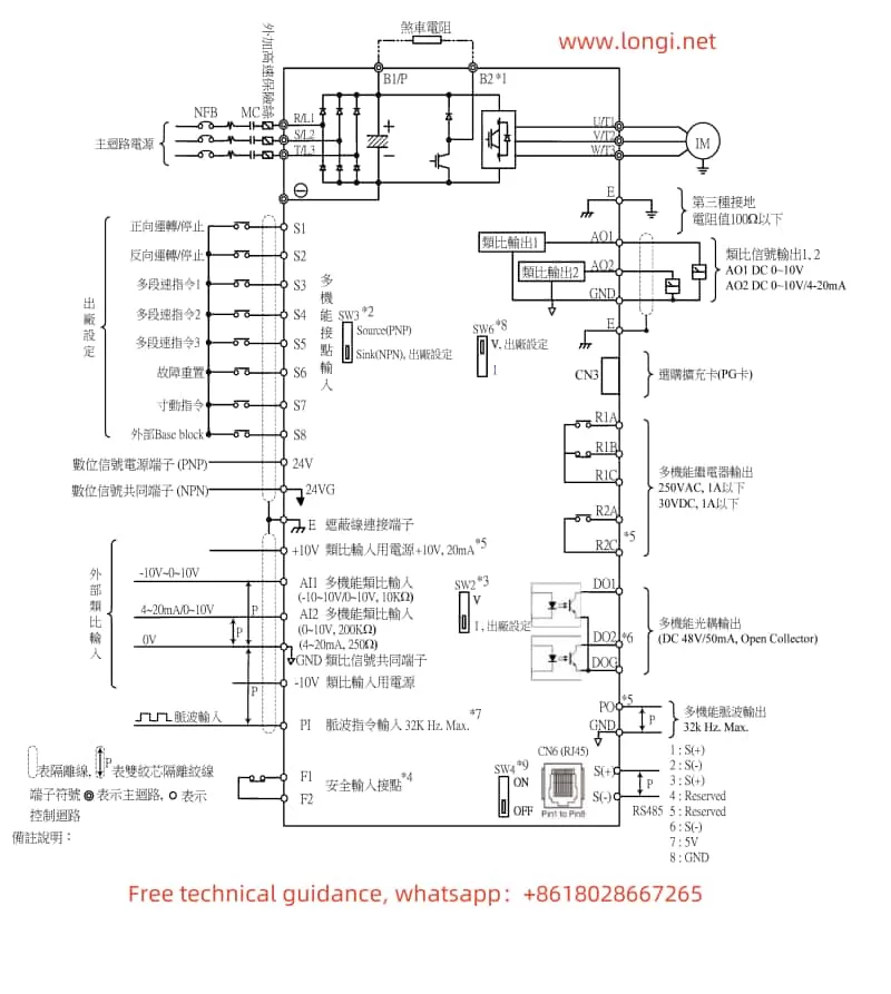
The TECO A510S series supports forward/reverse control and speed regulation via external terminals. Specific wiring and parameter settings are as follows:
Forward/Reverse Control:
To achieve forward/reverse control, users need to connect the multi-function digital input terminals (e.g., S1 and S2) of the converter to external control signal sources. In the parameter settings, set “Multi-function Terminal S1 Function Setting” (parameter 03-00) to 0 (forward/stop command) and “Multi-function Terminal S2 Function Setting” (parameter 03-01) to 1 (reverse/stop command). This way, when terminal S1 receives a high-level signal, the converter will rotate forward; when terminal S2 receives a high-level signal, it will rotate reverse.
External Potentiometer Speed Regulation:
External potentiometer speed regulation dynamically adjusts the converter’s output frequency via an analog signal (e.g., 0-10V or 4-20mA). Users need to connect the output end of the potentiometer to the converter’s analog input terminal (e.g., AI1 or AI2) and enable the corresponding analog input function in the parameter settings. For example, set the “AI1 Signal Scan Filter Time” (parameter 04-01) to an appropriate value to eliminate signal interference and set “AI1 Function Setting” (parameter 04-00) to 0 (0-10V input). Then, adjusting the potentiometer will change the converter’s output frequency.

III. Fault Code Meaning Analysis and Solutions
When a fault occurs in the TECO A510S series converter, it will display the corresponding error code, helping users quickly locate the problem. Below are some common fault code meanings and solutions:
- OC (Overcurrent): Indicates that the converter’s output current exceeds the rated value. Possible causes include motor overload, output short circuit, etc. Solutions include checking the motor load and examining the output circuit for shorts.
- OL1 (Motor Overload): Indicates motor overload. Possible causes include excessive load, too short acceleration time setting, etc. Solutions include reducing the load and increasing the acceleration time.
- OH1 (Heat Sink Overheat): Indicates inadequate converter cooling. Possible causes include high ambient temperature, faulty cooling fan, etc. Solutions include improving cooling conditions and replacing the cooling fan.
- UV (Undervoltage): Indicates that the input voltage is below the rated value. Possible causes include unstable power supply voltage and poor input circuit contact. Solutions include checking the power supply voltage and examining the input circuit connections.
IV. Conclusion
The TECO A510S series frequency converter user manual provides detailed operation guides and parameter setting instructions, helping users easily get started and efficiently operate and maintain the converter. Through this guide, users can learn how to operate the panel, set passwords and parameter locks, achieve terminal forward/reverse control and external potentiometer speed regulation, as well as interpret and solve common fault codes. The realization of these functions and application scenarios relies heavily on a thorough understanding and correct application of the user manual. Therefore, it is recommended that users carefully read the user manual before operating the converter and strictly follow the instructions for operation and settings.
