
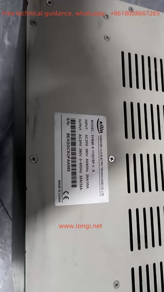
The Xilin EH600A series frequency converter is a high-performance inverter introduced by Shenzhen Xilin Electric Technology Co., Ltd. This guide provides detailed instructions on how to use the control panel, set up external control functions, and handle fault codes for the EH600A series.
I. Control Panel Features
1. Control Panel Functions
The control panel of the Xilin EH600A series integrates rich functionalities, allowing users to modify parameters, monitor status, and control operations such as start, stop, and forward/reverse. The main functions include:
- Parameter Modification: Users can modify various functional parameters, such as frequency settings, motor parameters, and control modes.
- Status Monitoring: The control panel displays the operating status, including output frequency, current, and voltage.
- Operation Control: Users can control the start, stop, and forward/reverse operations of the inverter.
2. Parameter Copying and Initialization
Parameter Copying
To copy parameters from one inverter to another:
- Use the dedicated communication software (e.g., the parameter setting software for EH600A) to export and save the parameters from the source inverter.
- Connect the target inverter to the computer via a communication cable and open the software.
- Import the saved parameters into the target inverter.
- Restart the target inverter to apply the parameters.
Parameter Initialization
To reset the inverter parameters to factory settings:
- Enter the parameter setting interface on the control panel.
- Locate the FD parameter group and set FD.10 (Parameter Initialization) to 1 (Restore Factory Settings).
- Save the parameters and restart the inverter to apply the factory settings.
3. Password Settings and Removal
Setting a Password
To prevent unauthorized access to parameter modifications:
- Enter the parameter setting interface on the control panel.
- Locate the F6 parameter group and set F6.08 (User Password) to a 4-digit number (e.g., 1234).
- Save the parameters. The system will prompt for the password the next time you enter the parameter setting interface.
Removing the Password
To disable the password protection:
- Enter the parameter setting interface using the current password.
- Set F6.08 to 0 and save the parameters.
- The password protection will be disabled.
4. Parameter Access Restrictions
To prevent unauthorized parameter modifications:
- Enter the parameter setting interface on the control panel.
- Locate the F6 parameter group and set F6.08 (User Password) to a non-zero value (e.g., 1234).
- Save the parameters. The system will prompt for the password the next time you enter the parameter setting interface.
II. External Control Functions
1. External Terminal Forward/Reverse Control
The EH600A series supports forward/reverse control via external terminals. The following steps outline the wiring and parameter settings:
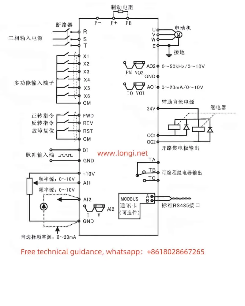
Wiring
- FWD (Forward): Connect to the forward control signal.
- REV (Reverse): Connect to the reverse control signal.
- CM (Common): Connect to the common terminal.
Parameter Settings
- Enter the parameter setting interface on the control panel.
- Locate the F3 parameter group and set F3.00 (X1 Terminal Function Selection) to 5 (Three-Wire Running Control).
- Set F3.06 (Terminal Command Mode) to 2 (Three-Wire Mode 1) or 3 (Three-Wire Mode 2), depending on the control logic.
- Save the parameters to enable external terminal forward/reverse control.
2. External Potentiometer Speed Control
The EH600A series supports speed control via an external potentiometer. The following steps outline the wiring and parameter settings:
Wiring
- AI1 (Analog Input 1): Connect to the signal terminal of the external potentiometer.
- GND (Ground): Connect to the ground terminal of the external potentiometer.
Parameter Settings
- Enter the parameter setting interface on the control panel.
- Locate the F0 parameter group and set F0.03 (Main Frequency Source X Selection) to 2 (AI1).
- Set F3.08 (AI1 Minimum Input) and F3.10 (AI1 Maximum Input) according to the potentiometer’s output range.
- Save the parameters to enable external potentiometer speed control.
III. Fault Codes and Handling
The EH600A series displays fault codes on the control panel when a fault occurs. The following table lists common fault codes, their meanings, and handling methods:
1. Common Fault Codes
| Fault Code | Description | Handling Method |
|---|---|---|
| E.1 | Inverter unit protection | Check the inverter unit for issues and replace if necessary. |
| E.OC1 | Overcurrent during acceleration | Reduce the load or adjust the acceleration time. |
| E.OC2 | Overcurrent during deceleration | Reduce the load or adjust the deceleration time. |
| E.OC3 | Overcurrent during steady operation | Reduce the load or adjust the frequency setting. |
| E.OU1 | Overvoltage during acceleration | Check the input voltage and adjust or replace the input fuse. |
| E.OU2 | Overvoltage during deceleration | Check the input voltage and adjust or replace the input fuse. |
| E.OU3 | Overvoltage during steady operation | Check the input voltage and adjust or replace the input fuse. |
| E.OU4 | Overvoltage during stop | Check the input voltage and adjust or replace the input fuse. |
| E.LU | Undervoltage during operation | Ensure the input voltage is stable and within the acceptable range. |
| E.OL1 | Inverter overload | Reduce the load or adjust the frequency setting. |
| E.OL2 | Motor overload | Reduce the load or adjust the motor parameters. |
| E.LF | Output phase loss | Check the output wiring for disconnections or poor contact and repair as needed. |
| E.OH | Inverter overheating | Check the cooling fan, clean the internal components, and replace the fan if necessary. |
| E.EF | External device fault | Check the external device for issues and resolve them. |
| E.CE | Communication fault | Check the communication lines and ensure the communication equipment is working properly. |
| E.GF | Output ground fault | Check the output wiring for grounding issues and repair as needed. |
| E.2 | CPU interference | Check the internal circuits for interference and replace the inverter if necessary. |
| E.3 | Current detection fault | Check the current detection circuit and replace the current detection module if necessary. |
| E.4 | EEPROM read/write fault | Check the EEPROM and replace it if necessary. |
| E.5 | Input phase loss | Check the input wiring for disconnections or poor contact and repair as needed. |
| E.6 | PID feedback disconnection | Check the PID feedback wiring for disconnections and repair as needed. |
2. Fault Handling Steps
- Identify the Fault Code: Check the control panel for the fault code and identify the fault type.
- Inspect Related Components: Based on the fault code description, inspect the related components of the inverter and external devices.
- Resolve the Fault: Follow the handling method to troubleshoot and resolve the fault.
- Restore Operation: After resolving the fault, restart the inverter and ensure it operates normally.
IV. Conclusion
The Xilin EH600A series frequency converter is a powerful and reliable device suitable for various industrial control applications. By effectively using the control panel functions, external control features, and promptly addressing fault issues, users can fully utilize the performance advantages of this inverter. This guide aims to provide valuable insights to help users better operate and maintain the EH600A series.