
I. Introduction to the Inverter Operator Panel Functions
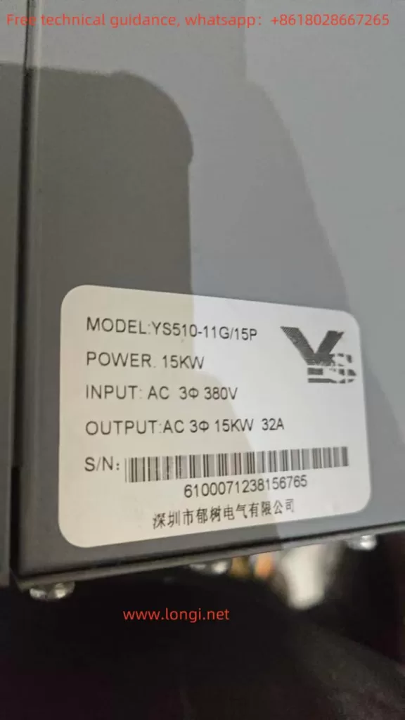
The Yushu Inverter YS510 series operator panel integrates a wealth of functions, enabling users to conveniently set parameters, monitor operating status, and diagnose faults. The operator panel primarily includes a digital display, function indicator lights, programming keys, data confirmation keys, shift keys, run keys, stop/reset keys, etc.
- Digital Display: Used to display key information such as the current operating frequency, set frequency, and fault codes.
- Function Indicator Lights: Such as RUN/TUNE (operating status indicator), FWD/REV (forward/reverse indicator), LOCAL/REMOT (control mode indicator), etc., to indicate the current operating status of the inverter.
- Programming Key: Used to enter or exit the parameter setting menu.
- Data Confirmation Key: Used to confirm the current parameter settings or enter the next menu level.
- Shift Key: Used to select different digits or functions during parameter setting.
- Run Key: Used to start the inverter.
- Stop/Reset Key: Used to stop the inverter or reset fault alarms.
II. Restoring Factory Default Settings
In certain situations, users may need to restore the inverter’s parameters to their factory settings. This can be achieved through the following steps:
- Enter the Parameter Setting Menu: Press the programming key to enter the parameter setting menu.
- Select Function Code F0.17: Use the shift key to select function code F0.17 (function parameter restore).
- Set the Parameter Value to 1: Enter the setting interface for function code F0.17 using the data confirmation key, set the parameter value to 1, and then confirm with the data confirmation key.
- Restore Factory Defaults: The inverter will automatically restore all parameters to their factory settings and display the “End” message, indicating that the restoration is complete.
III. Setting and Removing Passwords
To protect parameters from unauthorized modification, the Yushu Inverter YS510 series provides password protection. Users can set and remove passwords through the following steps:
Setting a Password
- Enter the Parameter Setting Menu: Press the programming key to enter the parameter setting menu.
- Select Function Code F7.00: Use the shift key to select function code F7.00 (user password).
- Enter the Password Value: Enter the desired password value (0~65535) in the setting interface for function code F7.00 using the data confirmation key, and then confirm.
Removing a Password
- Enter the Parameter Setting Menu: Press the programming key to enter the parameter setting menu.
- Select Function Code F7.00: Use the shift key to select function code F7.00 (user password).
- Set the Password Value to 0: Enter the setting interface for function code F7.00 using the data confirmation key, set the password value to 0, and then confirm. The password protection function will be disabled.
IV. Setting Parameter Access Restrictions
In addition to password protection, the Yushu Inverter YS510 series also provides parameter access restriction functions, allowing users to restrict access to specific function codes. This can be achieved through the following steps:
- Enter the Parameter Setting Menu: Press the programming key to enter the parameter setting menu.
- Select the Function Code Requiring Access Restriction: Use the shift key to select the function code requiring access restriction.
- Set Access Restriction: Enter the setting interface for the function code using the data confirmation key and set the access restriction to “not changeable” as needed (specific setting methods please refer to the inverter manual).
V. Copying Parameters to Another Inverter for Use
In certain situations, users may need to copy the parameters of one inverter to another for use. This can be achieved through the following steps:
- Use the Communication Interface: Ensure that both inverters support the Modbus communication protocol and connect them using a communication cable.
- Read Source Inverter Parameters: Use the upper computer software or programmer to read all parameters of the source inverter.
- Write to Target Inverter: Write the read parameters to the target inverter. Please note that before writing the parameters, ensure that the model and hardware configuration of the target inverter are the same as or compatible with the source inverter.
VI. External Terminal Forward/Reverse Control and External Potentiometer Speed Regulation
The Yushu Inverter YS510 series supports forward/reverse control and external potentiometer speed regulation through external terminals. The following are the specific wiring and parameter setting methods:
External Terminal Forward/Reverse Control
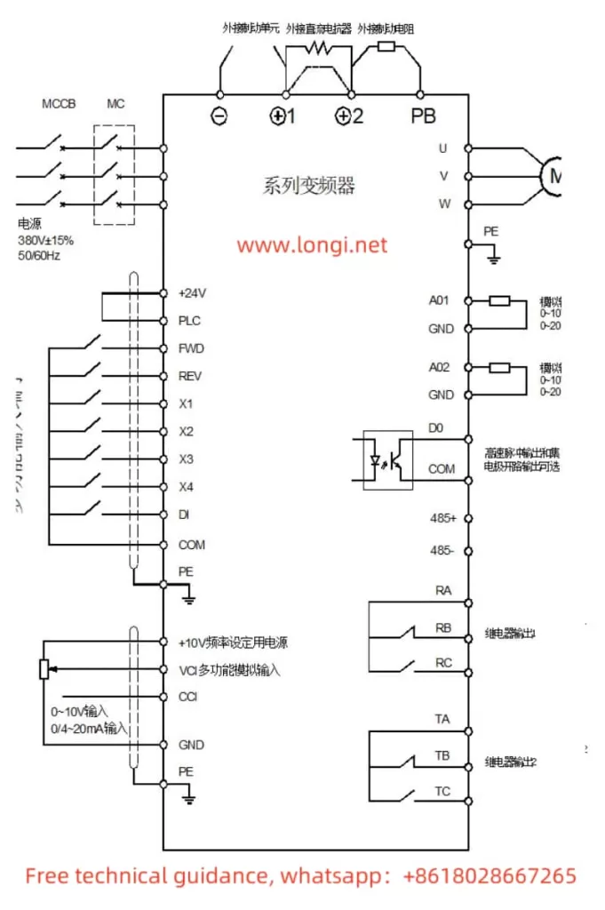
- Wiring:
- Connect the external forward control signal to the FWD terminal of the inverter.
- Connect the external reverse control signal to the REV terminal of the inverter.
- Ensure that the common terminal COM is correctly wired.
- Parameter Setting:
- Enter the parameter setting menu, select function code F5.06 (FWD terminal function selection), and set it to “forward operation” (usually 1).
- Select function code F5.07 (REV terminal function selection), and set it to “reverse operation” (usually 2).
- Ensure that function code F0.02 (run command channel) is set to “terminal command channel” (usually 1).
External Potentiometer Speed Regulation
- Wiring:
- Connect the output terminal of the external potentiometer to the analog input terminal VCI (or CCI, depending on the output type of the potentiometer) of the inverter.
- Ensure that the common terminal is correctly wired.
- Parameter Setting:
- Enter the parameter setting menu, select function code F0.03 (main frequency source X selection), and set it to “analog VCI setting” (or “analog CCI setting”, depending on the output type of the potentiometer).
- Adjust parameters such as function code F5.11 (VCI lower limit), F5.12 (VCI lower limit corresponding setting), F5.13 (VCI upper limit), and F5.14 (VCI upper limit corresponding setting) as needed to match the output range of the potentiometer.
评论 2626 条评论待审
VII. Fault Codes and Their Solutions
The Yushu Inverter YS510 series provides a wealth of fault codes to help users quickly locate and resolve fault issues. The following are some common fault codes, their meanings, and solutions:
- E-01: Acceleration Overcurrent
- Meaning: Overcurrent occurred during the acceleration process of the inverter.
- Solution: Check if the motor is overloaded, if the grid voltage is too low, if the inverter power is too small, etc., and appropriately increase the acceleration time.
- E-02: Deceleration Overcurrent
- Meaning: Overcurrent occurred during the deceleration process of the inverter.
- Solution: Check if the load inertia torque is too large, if the inverter power is too small, etc., and appropriately increase the deceleration time or add an appropriate energy dissipation brake component.
- E-04: Acceleration Overvoltage
- Meaning: Overvoltage occurred during the acceleration process of the inverter.
- Solution: Check if the input power supply is abnormal, if stopping and restarting are avoided, etc.
- E-07: Rectifier Module Overheat
- Meaning: The rectifier module of the inverter is overheated.
- Solution: Check if the inverter has an instantaneous overcurrent, if there is a phase-to-phase or ground short circuit in the output three-phase, if the air duct is blocked or the fan is damaged, etc., and take corresponding measures to resolve the issue.
- E-10: Motor Overload
- Meaning: The motor is overloaded.
- Solution: Check if the grid voltage is too low, if the motor rated current setting is correct, if the motor is jammed or the load suddenly changes too much, etc., and reset the motor rated current or check the load condition.
- E-15: Communication Fault
- Meaning: A communication fault occurred between the inverter and the upper computer.
- Solution: Check if the baud rate setting is appropriate, if the communication interface wiring is correct, etc., and reset using the STOP/RST key or seek service.
By thoroughly reading and understanding the Yushu Inverter YS510 series user manual, users can better master the operation methods and fault resolution techniques of the inverter, ensuring its normal operation and efficient use.