V&T Inverter V5-H Manual Usage Guide
I. Introduction to the Operation Panel Functions and Parameter Management
1.1 Introduction to the Operation Panel Functions
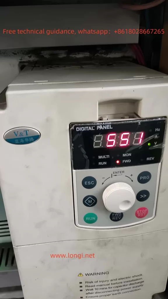
The V&T Inverter V5-H from Blue Ocean Huateng boasts an intuitive and easy-to-use operation panel that offers a wealth of control functions. The operation panel comes in two types: button-type and joystick-type, allowing users to choose based on their actual needs. The indicator lights on the operation panel provide a clear display of the current status of the inverter, such as frequency, current, voltage, and other parameters. Through keys like PRG (program key), ESC (exit key), and the rotary knob (+, -), users can conveniently access various menus for data setting and viewing.

1.2 Parameter Copy
The parameter copy function allows users to quickly replicate the parameters of one inverter to another, significantly improving setup efficiency. The specific operation steps are as follows:
- Connect the Operation Panel: Use the operation panel cable to connect the source inverter and the target inverter.
- Upload Parameters: On the source inverter, enter the operation panel menu, select the parameter upload function, and upload the parameters to the operation panel.
- Download Parameters: Connect the operation panel to the target inverter, select the parameter download function, and download the parameters from the operation panel to the target inverter.
1.3 Restore Parameter Initialization Settings
Restoring the parameter initialization settings can revert all parameters of the inverter to their factory defaults, making it convenient for users to reconfigure the parameters. The specific operation steps are as follows:
- Enter the operation panel menu and locate the “Function Code Protection” parameter (P0.01).
- Set P0.01 to “2”, then press the confirm key, and the inverter will restore all parameters except motor group parameters (P9 group) to their factory settings.
1.4 Set and Clear Passwords
To protect the inverter parameters from unauthorized modifications, users can set a password. The specific operation steps are as follows:
- Set Password: Enter the operation panel menu, locate the “User Password” parameter (P0.00), and set the same password twice consecutively to successfully set the password.
- Verify Password: Enter P0.00 again, input the correct password, and you will be able to access the parameter area protected by the password.
- Clear Password: After verifying the password, set P0.00 to “0000” to clear the password.
1.5 Set Parameter Access Restrictions
By setting parameter access restrictions, users can control the operation permissions of different users on the inverter. The specific operation steps are as follows:
- Enter the operation panel menu and locate the “Function Code Protection” parameter (P0.01).
- Set P0.01 to the desired value according to your needs, such as “1” to prohibit changes to all parameters, or “3” to restore all parameters except motor group parameters to their factory settings.
II. External Control and Speed Adjustment Settings
2.1 External Terminal Forward and Reverse Control
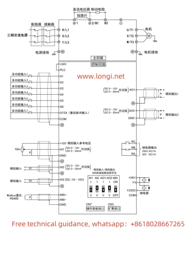
The V&T Inverter V5-H supports forward and reverse control of the motor through external terminals. Users need to connect the FWD (forward) and REV (reverse) terminals to the control signal source, such as a PLC or button switch. At the same time, corresponding parameters need to be set in the inverter:
- Enter the operation panel menu and locate the “Run Command Given Mode” parameter (P0.06).
- Set P0.06 to “1”, indicating that the run command is given through terminals.
2.2 External Potentiometer Given Frequency Speed Regulation
By connecting an external potentiometer to the AI1 (Analog Input 1) terminal of the inverter, users can achieve speed control of the motor frequency. The specific steps are as follows:
- Wiring: Connect the output terminal of the external potentiometer to the AI1 terminal of the inverter, and connect the COM terminal of AI1 to the common terminal of the inverter.
- Parameter Setting:
- Enter the operation panel menu and locate the “Open-Loop Main Given Mode” parameter (P0.04).
- Set P0.04 to “1”, indicating that the frequency is given by AI1 analog input.
- Set the AI1 analog input curve (P6.00) as needed to achieve linear or nonlinear speed regulation.

III. Fault Codes and Solutions
The V&T Inverter V5-H features a comprehensive fault diagnosis function that can display fault codes and fault information in real-time, helping users quickly locate problems. The following are some common fault codes, their meanings, and solutions:
3.1 E.oc1: Overcurrent Protection During Acceleration
Meaning: The inverter detects an overcurrent phenomenon during acceleration.
Solution:
- Check if the grid voltage is too low.
- Extend the acceleration time to reduce load mutation.
- Check if the motor parameter settings are correct.
- Consider replacing with a higher-power inverter.
3.2 E.oc2: Overcurrent Protection During Deceleration
Meaning: The inverter detects an overcurrent phenomenon during deceleration.
Solution:
- Extend the deceleration time.
- Use a suitable energy dissipation braking component.
- Check the motor parameter settings.
3.3 E.AUt: Self-Tuning Fault
Meaning: The inverter encounters a fault during self-tuning.
Solution:
- Ensure that the motor is in a stationary state before performing self-tuning.
- Check if the motor wires are properly connected and within the specified length.
- Reset the P9 group motor parameters according to the motor nameplate.
3.4 E.oL2: Motor Overload Protection
Meaning: The inverter detects motor overload.
Solution:
- Check if the load is too heavy or if the motor is jammed.
- Adjust the inverter overload protection parameters (P9.16, P9.18).
- Check if the motor is overheating, and replace it if necessary.
IV. Conclusion
The V&T Inverter V5-H manual provides users with detailed operation guides and troubleshooting methods. By mastering the functions of the operation panel and parameter setting methods, users can conveniently control and manage the inverter. At the same time, understanding common fault codes and their solutions can help users quickly locate and resolve issues, ensuring the stable operation of the inverter. In practical applications, users should also make flexible adjustments and optimizations based on specific needs and site conditions.
