I. Introduction to Servo Operation Panel Functions and Basic Settings
1.1 Panel Function Introduction
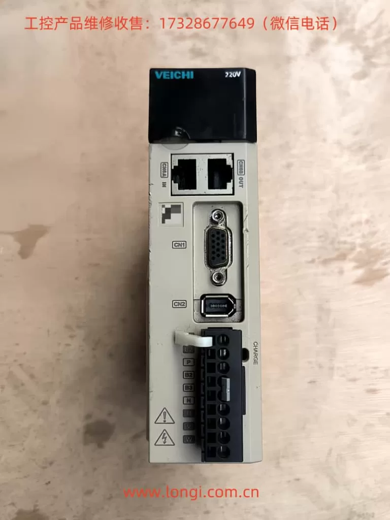
The WEICHI Servo SD710 series operation panel features a concise and clear design, including mode selection keys (MODE/SET), up/down adjustment keys (UP/DOWN), data shift keys (DATA/SHIFT), and some function keys. These keys allow users to easily switch modes, set parameters, display statuses, and more.

1.2 Setting Passwords and Parameter Access Restrictions
To ensure the security of the servo system, the SD710 series provides password protection functionality. Users can set the access permissions for function code parameters through parameter PnE1D’s system switch 3. The specific steps are as follows:
- Enter Auxiliary Functions: Press the MODE/SET key to select auxiliary functions and adjust to Fn010 using the UP/DOWN keys.
- Set Password: Press the DATA/SHIFT key for about one second to enter the parameter setting state, and adjust the parameter value using the UP/DOWN keys. Press the MODE/SET key to confirm after setting.
1.3 Realizing Jog Operation
Jog operation is a commonly used function in servo debugging. The SD710 series provides two modes: JOG (speed jog) and program JOG (position jog). The specific implementation steps are as follows:
- JOG Mode:
- Press the MODE/SET key to select auxiliary functions and adjust to Fn005.
- Set the jog speed (Pn500) using the UP/DOWN keys, and press the MODE/SET key to enter the servo ON state.
- Press the UP key (forward rotation) or DOWN key (reverse rotation) to start jog operation.
- Program JOG Mode:
- Press the MODE/SET key to select auxiliary functions and adjust to Fn006.
- Set the relevant parameters for program JOG (such as Pn502 operation mode, Pn503 movement distance, etc.).
- Press the MODE/SET key to enter the servo ON state and start program JOG operation.

1.4 Setting Brake and Over-travel
Brake Setting:
- Set the relevant delay times for brake activation through parameters Pn009 and Pn010 to ensure that the brake can actuate timely when the motor stops.
Over-travel Setting:
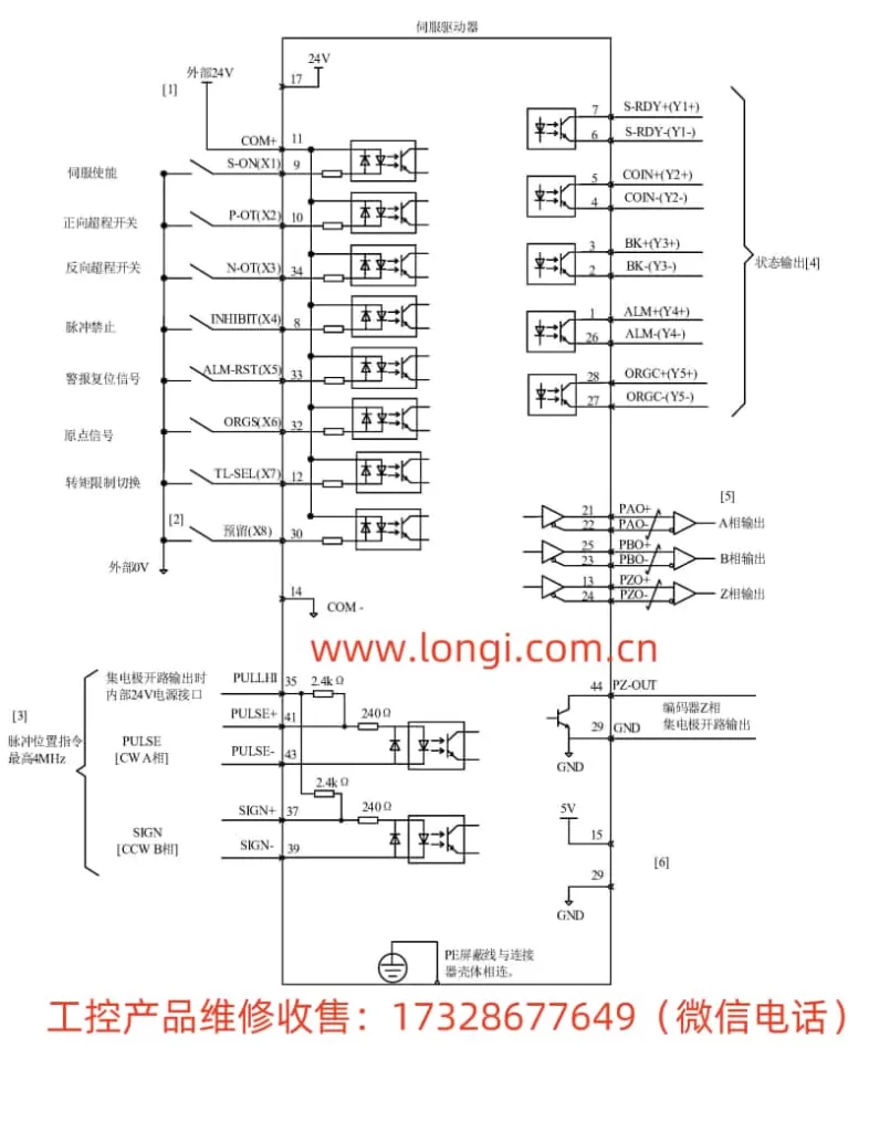
- Connect external limit switches to the P-OT and N-OT pins of the CN1 terminal to achieve over-travel protection in positive and negative directions.
- Alternatively, enable the soft limit function internally through parameter Pn00D.W and set the absolute position limit switch.
1.5 Regenerative Braking Setting
Regenerative braking is an important safety protection function in servo systems. The SD710 series provides options for both built-in and external regenerative braking resistors. Users can set the resistance and capacity of the built-in braking resistor through parameters PnE0B and PnE0C. For external braking resistors, correct connection according to the wiring diagram in the drive manual is required, and the corresponding resistance should be set through parameters.
II. External Pulse Position Mode Forward and Reverse Positioning Control
2.1 Terminal Connections
To realize external pulse position mode forward and reverse positioning control, the relevant pins of the CN1 terminal need to be connected correctly. The specific connections are as follows:
- Pulse Input: Connect to the PUL+ and PUL- pins of CN1.
- Direction Input: Connect to the DIR+ and DIR- pins of CN1.
- Enable Input: Connect to the S-ON pin of CN1.
2.2 Parameter Settings
- Control Mode Selection: Set parameter Pn000.X to 0 to select position control mode.
- Position Command Source Selection: Set parameter Pn200 to 0 to select external pulse sequence as the position command source.
- Electronic Gear Ratio Setting: Set parameters Pn204 (numerator) and Pn206 (denominator) according to actual needs to determine the number of pulses per motor revolution.
- Jog Speed Setting (optional): Set parameter Pn500 for using the jog function during debugging.
After completing the above settings, pulse signals can be sent through an external pulse generator to realize forward and reverse positioning control of the servo motor.

III. Fault Codes and Solutions
The WEICHI Servo SD710 series drive provides a wealth of fault codes to help users quickly locate problems. The following are some common fault codes and their solutions:
- ER.020: User function code parameter and checksum error. Solution: Check if the parameter settings are correct and re-initialize the parameters after re-powering.
- ER.100: Drive overcurrent. Solution: Check if the motor and drive are overloaded, and check if the motor power line connection is poor.
- ER.320: Regenerative overload. Solution: Check if the regenerative braking resistor is connected correctly and if the resistance is appropriate; reduce the load or increase the braking resistor.
- ER.400: Overvoltage. Solution: Check if the power supply voltage is stable and if it exceeds the rated voltage range of the drive.
- ER.410: Undervoltage. Solution: Check if the power supply voltage is too low and ensure that the power supply voltage is within the allowable range of the drive.
For other fault codes, users can refer to the fault code table in the drive manual and perform corresponding checks and troubleshooting according to the prompts.
IV. Conclusion
The WEICHI Servo SD710 series user manual provides detailed operation guides and parameter setting instructions, helping users quickly get started and achieve efficient and stable servo control. By correctly setting panel parameters, connecting external terminals, and promptly handling fault codes, users can fully leverage the performance advantages of the SD710 series to meet the needs of various industrial applications.
