Posted on Leave a comment

Diagnosis and Resolution of “Free Stop” Fault in ENC EDH2200 High-Voltage Inverter: Impact of S1# Function Configuration

Introduction

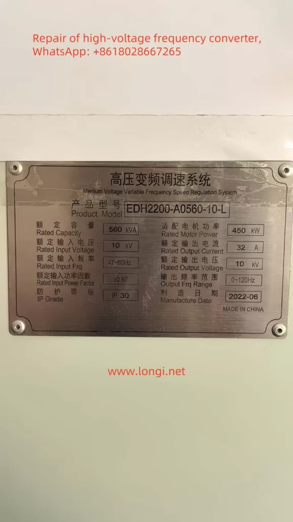
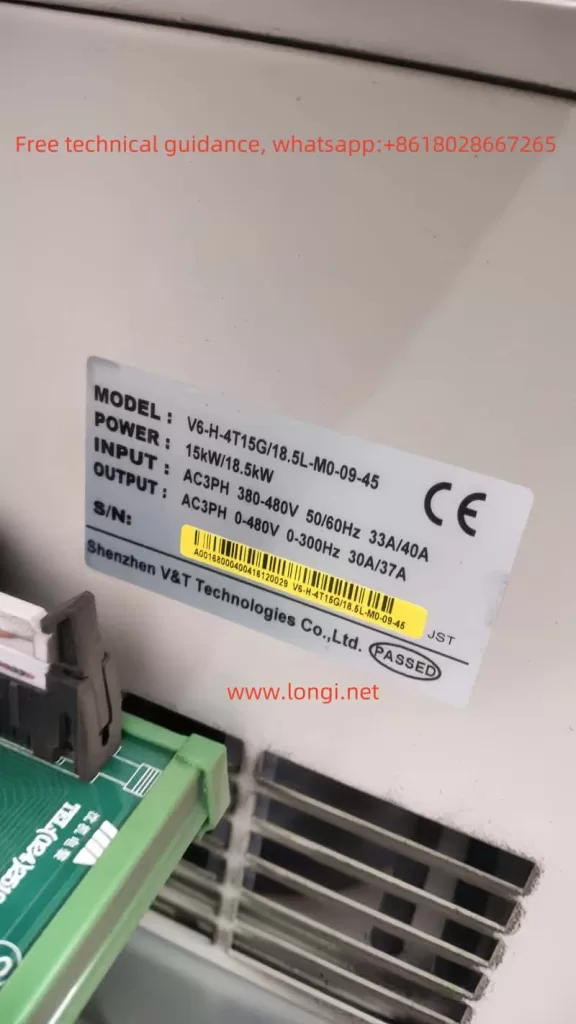
The ENC EDH2200 series high-voltage inverter is commonly used in industrial applications for motor control. However, during operation, it may enter a “free stop (emergency stop)” state due to faults, rendering it unable to restart. Based on an actual case, this article analyzes the causes of the inverter’s “free stop” fault, focusing on the impact of the input terminal S1# function configuration (P05.00), and summarizes solutions and preventive measures.

Fault Background

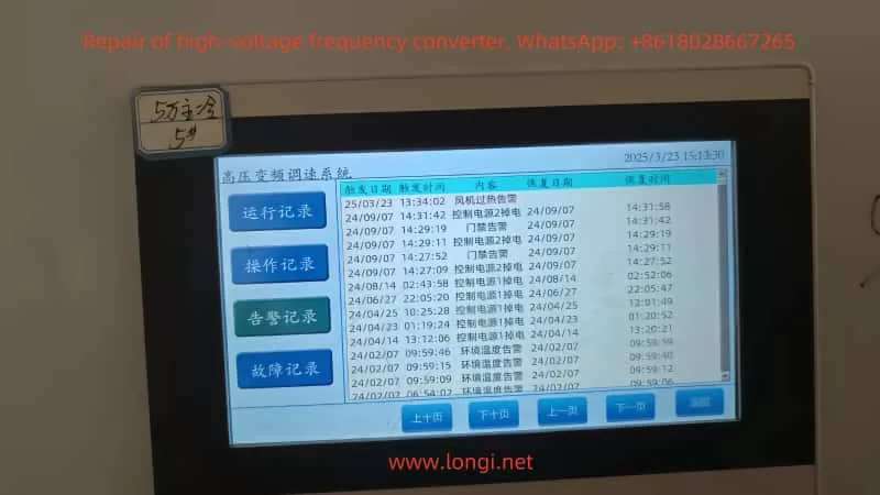
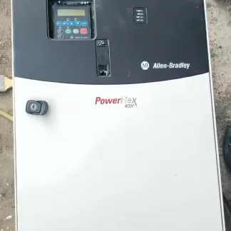
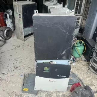
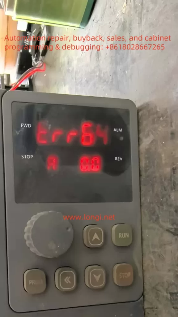
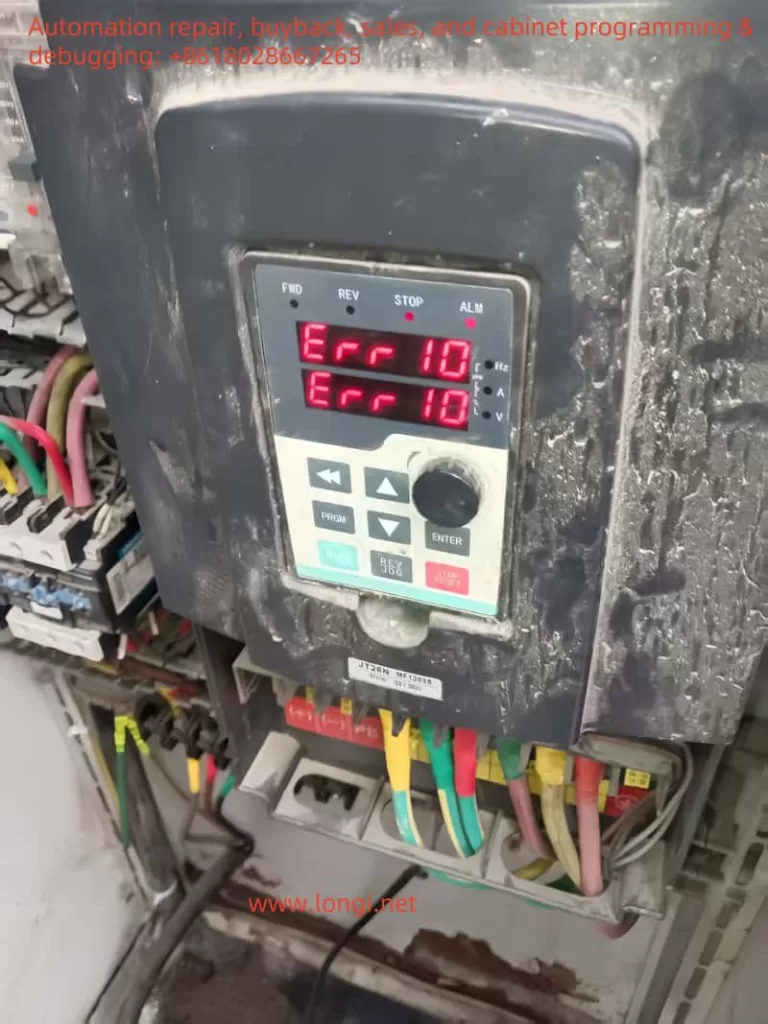
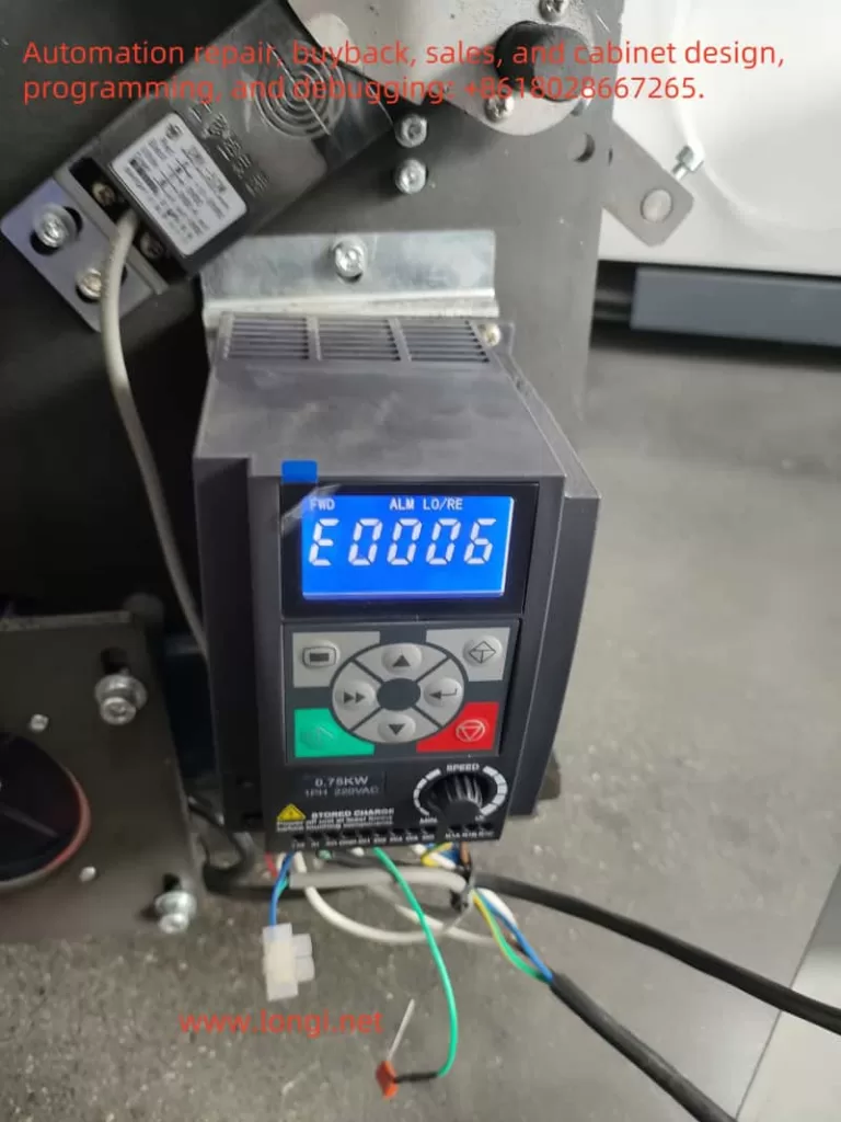
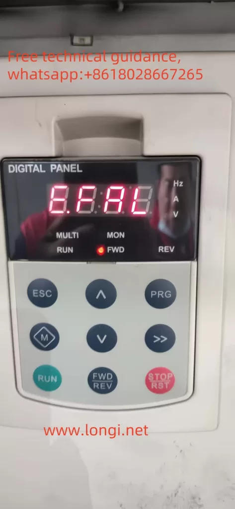
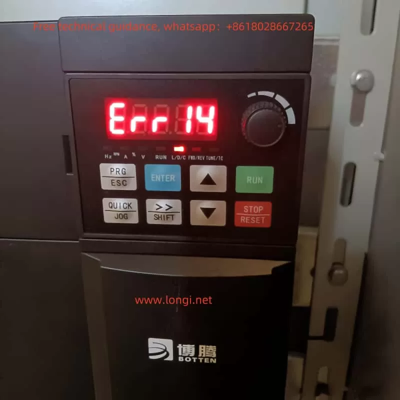
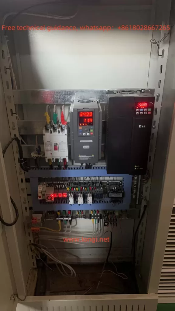
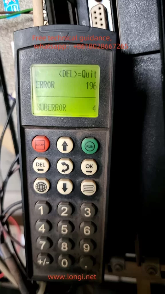
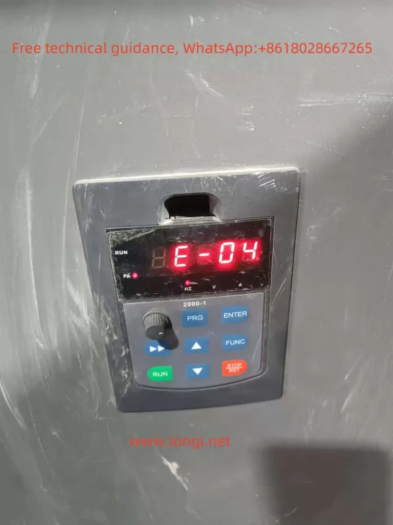
The inverter control panel (Attachment 5.jpg) displays an “actual alarm POFF state,” with operational parameters at 0 (input/output voltage 0V, current 0A, frequency 0Hz), indicating the system is in a non-operational state. The operation log (Attachment 1.jpg) shows S3# as “self-generated accident (total accident),” initially considered the root cause. However, after adjusting the S1# terminal function (P05.00) from “1: Lift given” to “0: No function,” the system returned to normal, and the inverter successfully restarted.

Emergency stop state

Fault Cause Analysis

Based on the operation log and the actual resolution process, the following is a detailed analysis of the fault causes:

  1. Impact of S1# Function Configuration
    • P05.00 (S1# function selection) was originally set to “1: Lift given,” likely used to receive signals from external devices (e.g., pump lift control signals).
    • If the external device fails to provide a correct signal (e.g., signal loss, abnormality, or interference), the system may misjudge it as a fault and trigger a protection mechanism, leading to “free stop.”
    • Changing P05.00 to “0: No function” removes S1# from control, and the system exits the protection state, indicating that the S1# configuration is the core issue.
  2. Correlation with S3# “Self-Generated Accident”
    • S3# (P05.02) displays “self-generated accident (total accident),” which may be a chain reaction triggered by S1# malfunction.
    • The inverter’s protection logic may be designed to trigger a total accident (S3#) and enter emergency stop mode when an abnormality is detected on a terminal (e.g., S1#).
  3. Possible External Factors
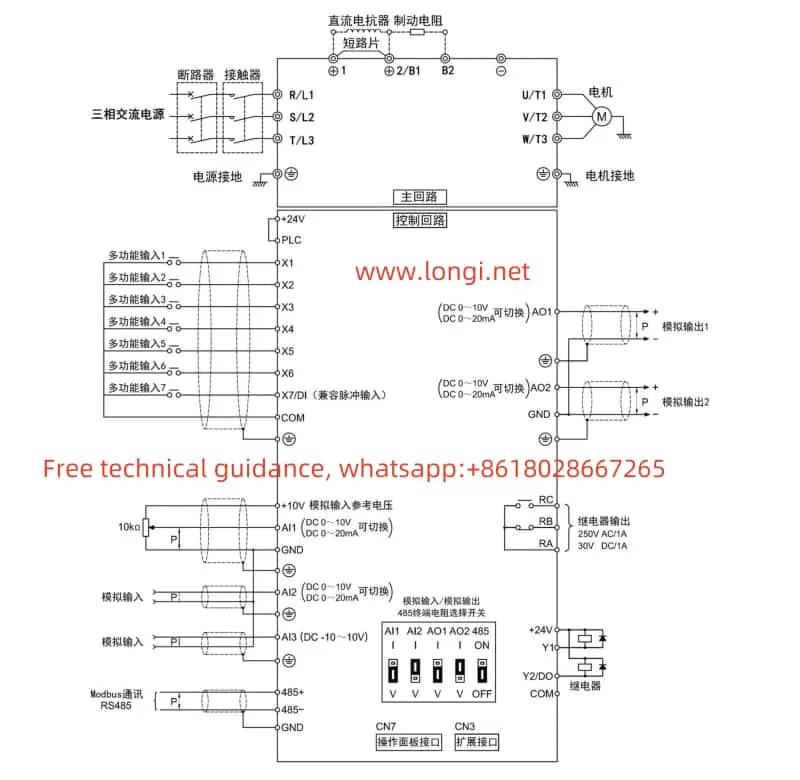
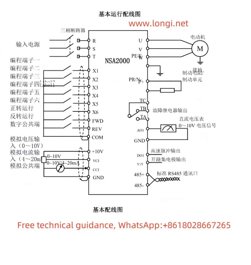
    • S1# may be connected to external devices (e.g., pumps or sensors). If the device malfunctions or there are wiring issues (e.g., loose connections, short circuits), it may cause signal abnormalities.
    • Environmental interference (e.g., electromagnetic interference) may also affect S1# signal transmission.
  4. Hardware and Parameter Configuration
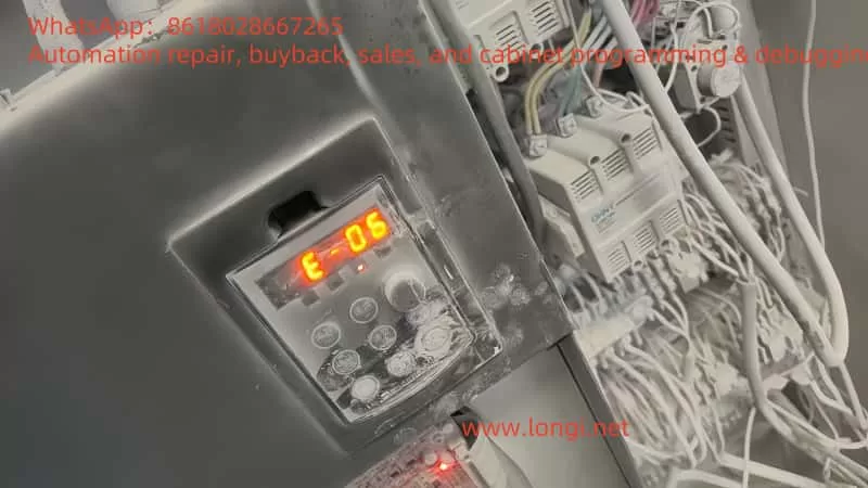
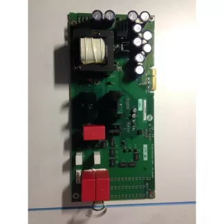
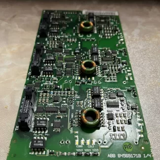
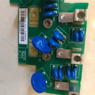
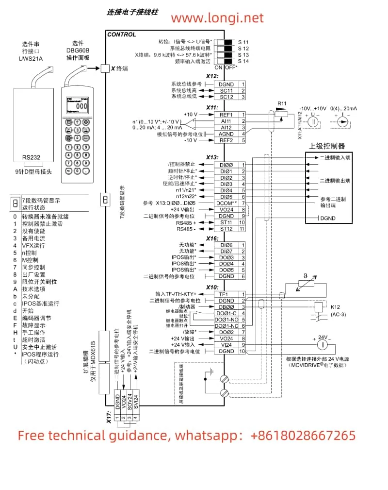
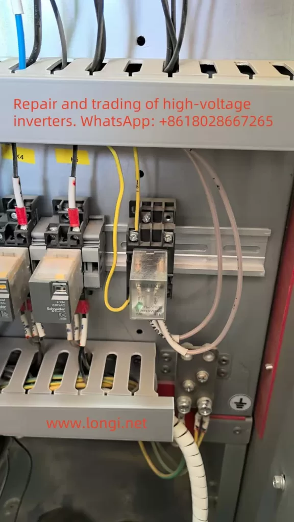
    • Circuit board images (Attachments 3.jpg and 4.jpg) show relays K4/K5 and terminal connections. If S1#-related hardware is damaged, it may cause signal errors.
    • Improper configuration of P05 group parameters (input terminal function selection) may lead to system misjudgment.
Control circuit inside the high-voltage inverter cabinet

Resolution Process

  1. Problem Identification
    • The control panel displays “POFF state,” and the operation log shows S3# as “self-generated accident.” However, the “lift given” function of S1# raises concerns.
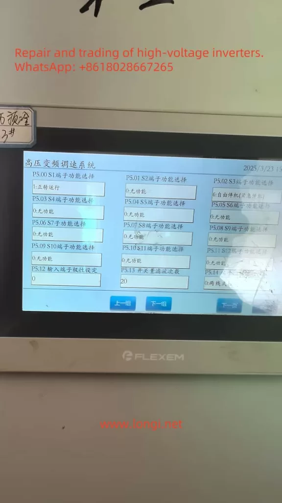
    • Referencing the P05 group parameter table (Attachment 6.jpg), it is confirmed that S1# (P05.00) is set to “1: Lift given.”
  2. Parameter Adjustment
    • Change P05.00 from “1” to “0” (no function) to remove S1# from control.
    • After adjustment, use the control panel’s “reset” function to clear the alarm.
  3. System Recovery
    • Press the “start” button, and the inverter successfully restarts with operational parameters returning to normal (voltage, current, frequency, etc., no longer 0).

Summary of Solutions

  • Core Solution Steps: Change P05.00 (S1# function) from “1: Lift given” to “0: No function,” remove S1#’s control function, clear the alarm, and restart the system.
  • Preventive Measures:
    • Check S1#’s wiring and external devices to ensure normal signal transmission.
    • Regularly maintain hardware to prevent loose connections or component damage.
    • Record parameter adjustments for future troubleshooting.

Unexpected Findings

  • The S3# “self-generated accident” record may only be a result, not the cause. The actual issue stems from the S1# configuration. This highlights the need to consider all relevant terminals and parameters when troubleshooting inverter faults, rather than focusing solely on alarm records.
  • The control panel brand is FLEXEM, while the inverter is ENC, which may involve terminological or logical differences. For example, the “POFF” state is defined in FLEXEM but not explicitly mentioned in the ENC manual.
EDH2200 terminal board

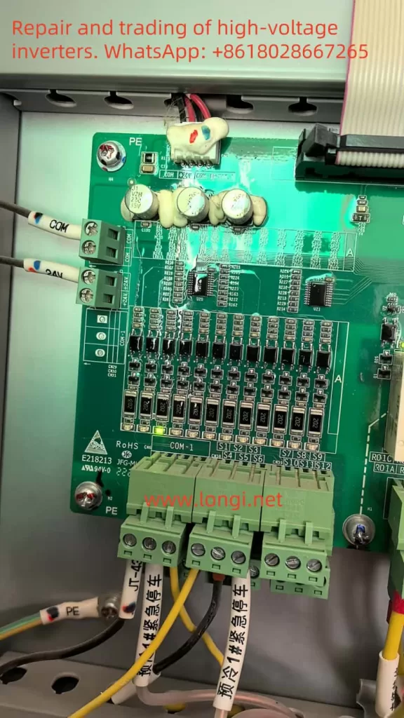
Table: Fault Causes and Solutions

Fault PhenomenonPossible CauseSolution
Free stop, unable to startS1# function (lift given) mis-triggerChange P05.00 to “0: No function”
S3# displays self-generated accidentChain reaction from S1# abnormal signalClear alarm after resolving S1# issue
System displays POFF stateProtection mechanism triggers power-offRestart system after clearing alarm
External device signal abnormalityLoose wiring or device faultCheck S1# wiring and external devices

Conclusion

The “free stop (emergency stop)” issue in the ENC EDH2200 high-voltage inverter is caused by improper configuration of the S1# terminal function (P05.00), potentially triggered by abnormal external signals. By changing the S1# function to “no function,” the system returns to normal. Users are advised to regularly check terminal wiring and external devices, optimize parameter configurations, and take preventive measures to avoid recurrence of similar issues.

Posted on Leave a comment

Analysis and Solutions for Fan Overheating Fault in ENC EDH2200 High-Voltage Inverter

Introduction

Variable Frequency Drives (VFDs) are critical devices for controlling motor speed and torque in modern industrial applications. However, fan overheating alarms are a common fault during inverter operation. This document provides a comprehensive analysis of the fan overheating alarm issue in the ENC EDH2200 series high-voltage inverter, covering its meaning, possible causes, solutions, and operational log analysis to guide users in troubleshooting and resolving the problem.


Fault Meaning

fan overheating alarm indicates that the cooling fan of the inverter has exceeded its temperature threshold, potentially affecting normal device operation. As a key component for internal temperature control, the fan’s failure to cool the system effectively will lead to temperature rises, trigger protection mechanisms, and may even damage electronic components or cause system failures.
Key Detail: The operational log shows the alarm occurred at 13:34:02 on March 25, 2023, with a recovery time recorded as 14:31:58 on September 7, 2024. The abnormally long alarm duration requires urgent attention.


The alarm for fan overheating

Possible Causes

  1. Excessive Ambient Temperature
    • The operating environment temperature exceeds the inverter’s default threshold of 75°C, causing the fan to run continuously for extended periods and overheat.
    • Manual Parameter: P08.27 sets the ambient temperature alarm threshold; verify if the actual temperature exceeds the limit.
  2. Fan Malfunction
    • Damage to the fan motor or obstruction of blades leads to insufficient cooling.
    • Manual Parameter: P23 group parameters (e.g., P23.20 and P23.21) control fan start/stop temperatures; these may fail if the fan malfunctions.
  3. Ventilation Blockage
    • Dust, debris, or internal accumulations block ventilation ports, impeding airflow.
    • Preventive Measure: Regularly clean the ventilation system.
  4. Overload
    • The connected load exceeds the inverter’s rated capacity, increasing heat generation and burdening the fan.
    • Solution: Ensure the load is within the inverter’s specifications.
  5. Improper Parameter Settings
    • Incorrect configuration of temperature control parameters results in inappropriate fan start/stop conditions.
    • Manual Parameter: Adjust P23.03 (overheat warning temperature 1, default 90°C) and P23.04 (default 110°C) based on actual conditions.

Solutions

  1. Check and Control Ambient Temperature
    • Measure the current ambient temperature and ensure it remains below the 75°C threshold.
    • If the temperature is too high, install air conditioning or improve ventilation (e.g., add exhaust fans).
  2. Maintain and Inspect the Fan
    • Ensure the fan operates normally and check for damage or wear to the motor and blades.
    • If a fault is detected, replace damaged components by referring to Section 8.5 of the manual.
    • Regularly clean the fan to remove dust or blockages.
  3. Optimize the Ventilation System
    • Ensure sufficient space around the inverter to meet ventilation requirements in the manual.
    • Clean ventilation ports and surrounding areas to prevent dust accumulation.
  4. Verify Load and Inverter Capacity
    • Check if the current load exceeds the inverter’s rated capacity; if so, reduce the load or upgrade the inverter.
    • Ensure compatibility between the motor and the inverter.
  5. Adjust Parameter Settings
    • Modify P23 group parameters based on actual needs (e.g., increase P23.03 to an appropriate value, but do not exceed 135°C).
    • Ensure P23.20–P23.23 settings align with actual operating conditions.

Operational Log Analysis

  • Key Log Entries:
    • March 25, 2023, 13:34:02: Fan overheating alarm triggered. Recovery time recorded as September 7, 2024, 14:31:58, indicating an abnormally long alarm duration that may not have been resolved promptly.
    • Multiple ambient temperature exceedance warnings (e.g., repeated records on February 7, 2024) support the hypothesis of excessive ambient temperature.
  • Unexpected Detail: Inconsistent dates in the log (recovery time later than the alarm time) suggest a potential error in the system’s logging mechanism.
    • Recommendation: Check the system clock and logging function to ensure data accuracy.

EDH2200

Conclusion

Resolving the fan overheating alarm in the ENC EDH2200 series high-voltage inverter requires a systematic investigation of potential causes and the implementation of the following measures to manage and prevent issues:

  • Control ambient temperaturemaintain the fanoptimize ventilationverify load, and adjust parameters.
    Regular maintenance and monitoring are critical to ensuring the long-term reliability of the inverter.

Key Highlight: Prioritize addressing the inconsistent dates in the operational log to avoid misdiagnosis caused by logging errors.

Posted on Leave a comment

SHZHD.V680 Variable Frequency Drive E-06 Fault Analysis and Solutions

1. Fault Overview

The E-06 fault indicates a deceleration overvoltage, a common issue that can occur during the deceleration process of the SHZHD.V680 variable frequency drive. When the output voltage exceeds the safe range during deceleration, the drive triggers a protection mechanism, leading to equipment shutdown or alarms. This fault is often related to motor load characteristics, parameter settings, and over-excitation control.

2. Fault Cause Analysis

  • Improper Over-Excitation Settings: Low over-excitation gain settings can cause the voltage to rise too quickly during deceleration.
  • Load Characteristics: Loads with high inertia can generate excessive reverse electromotive force during deceleration.
  • Unreasonable Parameter Settings: Short deceleration times can cause the voltage to rise too quickly during deceleration.
E-05

3. Solutions

3.1 Adjust Over-Excitation Gain
  • Parameter P3-10 (VF Over-Excitation Gain): Increase this value to better suppress voltage rise during deceleration. Recommended range: 0 ~ 200. Gradually increase based on actual conditions until the fault is resolved.
3.2 Optimize Deceleration Time Settings
  • Parameter P0-18 (Deceleration Time 1): Extend the deceleration time to make the deceleration process smoother. Gradually increase based on actual load characteristics until the fault is resolved.
3.3 Check Load Characteristics
  • If the load has high inertia, additional braking measures, such as adding a braking resistor or using a regenerative system, may be necessary during deceleration.
3.4 Check Motor and Drive Compatibility
  • Ensure that the motor and drive parameters are matched to avoid overvoltage issues due to mismatched parameters.

4. Precautions

  • Adjust parameters gradually to avoid introducing other issues.
  • Conduct trial runs after adjustments to confirm that the fault has been resolved.
  • If the problem persists, consult technical support or a professional repair technician for further diagnosis.
SHZHEND.V680

5. Conclusion

By appropriately adjusting the over-excitation gain, optimizing deceleration time settings, checking load characteristics, and ensuring motor and drive compatibility, the E-06 deceleration overvoltage fault in the SHZHD.V680 variable frequency drive can be effectively resolved. Proper parameter settings and regular maintenance are key to ensuring the efficient operation of the drive.

Posted on Leave a comment

M900 Inverter err64 Fault: Meaning, Root Cause Analysis, and Solutions

M900 Inverter err64 Fault: Meaning, Root Cause Analysis, and Solutions

(This article discusses the background of the “err64” fault in M900 series inverters, its potential causes, deeper hardware-level analyses, and practical troubleshooting steps. The goal is to help electrical maintenance personnel target the problem more effectively. This text, of over 1,000 words in its Chinese original, covers both theoretical and hands-on repair perspectives.)


I. Background and Meaning of err64

In typical inverter applications, the most common faults involve overcurrent, overvoltage, undervoltage, overload, and cooling fan issues. However, in certain cases—especially after repairs or the replacement of internal components—M900 inverters may display a “err64” fault code. According to the manufacturer’s technical support, “err64” is not listed in the usual user manual but indicates a communication failure between the main control board and the driver board.

In other words, the inverter’s primary control circuitry (often referred to as the “master” or “main” board) and its power drive unit (“driver” board) cannot exchange data, causing the control system to fail to operate properly and thus triggering a fault protection.

To understand this issue, one must note that an M900 inverter typically consists of at least two major sections: a control board (hosting the microcontroller or DSP as the core of the logic) and a driver board (housing the power modules, IGBTs, or related gate driver circuitry). These boards communicate via a dedicated interface or set of pins. Sometimes, there may also be a small power supply board or other auxiliary boards, but the communication link between the main board and the driver board is central to the entire system. Once that link is broken or corrupted, the inverter will report a “board-to-board communication error” such as “err64” and shut down to protect itself.


II. Common Causes of err64

  1. Loose or Faulty Ribbon Cable/Connector
    During maintenance or reassembly, a ribbon cable or connector might not have been fully seated, or its metal pins could be bent, oxidized, or otherwise damaged. This often leads to poor signal transmission or no transmission at all, and is one of the most frequent root causes for communication errors.
  2. Damaged Hardware Chips
    • Burned-out Transceiver/Bus Chip: The communication between the control and driver boards usually involves specialized transceiver components (e.g., RS485 driver chips, optical isolators, or TTL level transceivers). If subjected to excessive heat, current surge, or electrostatic discharge, these chips can fail and interrupt the data link.
    • Main CPU or Driver DSP Failure: Though less common, serious power surges, extended over-temperature conditions, or short-circuit mishandling can damage the main controller or DSP on either board. When that happens, the inverter can no longer exchange valid data, triggering the err64 alarm.
  3. Auxiliary Power Supply Issues
    The main board and driver board typically rely on a regulated power supply—often +5V or +3.3V—to operate their digital circuits. If this low-voltage supply is weak or unstable, or if a regulator (LDO, DC-DC converter) on either board is failing, then even intact chips may produce garbled signals and fail to establish proper communication.
  4. Secondary Damage During Fan or Relay Replacement
    Many reported err64 errors occur soon after a user replaces a fan or relay. This suggests that the process may introduce secondary problems:
    • An incompatible relay or altered circuit parameters causing abnormal power conditions;
    • Accidental short-circuits or soldering damage during the repair;
    • The inverter may already be partially degraded from prior overheating, so additional stress completes the failure pathway.

III. Root Cause Analysis and Troubleshooting

At its core, “err64” represents an internal communication failure. This communication is usually a low-level or custom protocol rather than a typical external fieldbus (like Modbus). As a result, the inverter’s diagnostic does not offer many granular details. Because the issue can lie in various hardware points, it is best to follow a structured approach:

  1. Physical Inspection and Connector Checks
    • First, turn off power and wait long enough for internal capacitors to discharge (generally at least 10 minutes).
    • Open the inverter casing to inspect all connectors, paying particular attention to the flat cables and sockets between the main board and driver board. Look for signs of looseness, oxidation, broken plastic housings, or bent pins.
    • Clean off any dust or grime with an appropriate solution such as isopropyl alcohol. Dry thoroughly, re-seat the connectors firmly, then restart and see if the error persists.
    • This preliminary step is simple but can resolve many “false” faults that arise after vibrations or reassembly.
  2. Supply Rails and Signal Tests
    • Use a multimeter to check the low-voltage rails (+5V, +3.3V, etc.) on both the control and driver boards. Confirm stable, correct output levels.
    • If available, use an oscilloscope to observe the communication pins (TX, RX, or RS485 differential signals) for pulses or signals. If the line is held at a steady voltage with no pulses, it indicates that the transmitter is not functioning (which could mean the transceiver or even the CPU is compromised).
    • If the signal is noisy or the amplitude is too low, consider the possibility of defective coupling resistors, capacitors, or the transceiver chip itself.
  3. Suspecting Transceiver or MCU Failure: The Swap/Replacement Method
    • After verifying connectors, supply rails, and passive components, you may try replacing the communication transceiver chip with one of the same model if you suspect it is burned out.
    • If replacing the transceiver chip does not help, the fault may lie in the main CPU, driver DSP, or other major components on the board. Diagnosing or replacing these can require specialized tools and is best handled by trained professionals.
  4. Reset to Factory Defaults or Firmware Update
    • Occasionally, firmware or software anomalies can also trigger internal communication timeouts.
    • Attempt a factory reset (restoring default parameters) and then power up again to see if the fault clears. If the manufacturer provides a firmware update procedure, you can try upgrading the system firmware. However, if the hardware is physically damaged, these software-level attempts typically will not resolve an err64 alarm.

IV. Precautions and Preventive Measures

  1. Prompt Cooling System Maintenance
    If the M900 inverter’s cooling fan stops working or its venting is blocked, the internal boards can operate at high temperatures, accelerating aging. Quick repair or replacement of fans can prevent serious damage that leads to communication issues.
  2. Standardized Repair Operations
    • Always allow adequate discharge time after powering off the inverter to avoid electric shock or component damage.
    • When replacing a relay or other parts, match the specifications (coil voltage, contact ratings, etc.) exactly.
    • Proper soldering tools and techniques are crucial—poorly done solder joints or bridging can damage sensitive PCB traces and components.
  3. Cleanliness and Protective Practices
    • In dusty or humid environments, regularly open the inverter casing for an internal check and cleaning.
    • If connectors or components show corrosion or rust, replace or clean them promptly.
    • Perform these repairs or inspections in as clean an environment as possible, avoiding metal particles, oil, or fine dust contamination on open circuit boards.
  4. Fault Log and Data Recording
    • If the inverter can store internal logs or provide real-time data, document those details as soon as a fault appears.
    • Observing the inverter’s normal operating waveforms versus the state just before a failure can guide you to the precise area of malfunction.

Conclusion

In summary, an M900 inverter reporting “err64” indicates a lost or compromised communication link between its main control board and driver board. This can stem from something as simple as a partially inserted ribbon cable or can be as severe as a failed bus transceiver chip or main CPU.

The recommended troubleshooting approach is systematic:

  1. Inspect and re-seat cables and connectors;
  2. Verify supply voltages and signals;
  3. Replace suspect transceiver and check associated passive parts;
  4. Finally, if those attempts fail, look toward the main CPU, DSP, or more advanced board-level repairs.

Meanwhile, ensuring proper cooling, following proper service procedures, and regularly cleaning the inverter’s internals will significantly lower the likelihood of such communication failures. If all methods are exhausted, contacting a professional repair center or the manufacturer is advisable for advanced diagnostics. By fully understanding the root cause and progression of “err64” faults, you can remedy them swiftly and maintain the M900 inverter’s reliability for critical industrial processes.

Posted on Leave a comment

JTE Inverter JT26N Usage Guide and ERR10 Fault Resolution

The JTE Inverter JT26N series is a high-performance general-purpose inverter widely used in various industrial control scenarios. This article provides a detailed introduction to the usage of this inverter, including panel startup and speed adjustment settings, external terminal forward/reverse and external potentiometer speed adjustment settings, parameter copying and initialization methods, as well as the meaning and resolution of the ERR10 fault.

JT26N physical image

I. Basic Settings for the JTE Inverter JT26N

1. Panel Startup and Speed Adjustment Settings

The panel startup and speed adjustment settings for the JTE Inverter JT26N are relatively straightforward. Users can complete basic startup and speed adjustment operations through the buttons and display on the control panel. Here are the specific steps:

  1. Startup Settings:
  • Press the “PRGM” key to enter programming mode.
  • Use the “Δ” and “∇” keys to select the function code F0-02, and confirm that the command source is set to the control panel command channel (value 0).
  • Press the “ENTER” key to confirm the setting.
  1. Speed Adjustment Settings:
  • In programming mode, select the function code F0-03 and set the main frequency source X to panel potentiometer speed adjustment (value 1).
  • Adjust the frequency by rotating the potentiometer on the panel to achieve speed control.

2. External Terminal Forward/Reverse and External Potentiometer Speed Adjustment Settings

The JTE Inverter JT26N supports forward/reverse control and external potentiometer speed adjustment functions through external terminals. Here are the specific wiring and setup methods:

  1. Forward/Reverse Control:
  • Wiring: Connect the external control signal to the digital input terminals of the inverter (such as MI1, MI2, etc.).
  • Settings: In programming mode, select the function code F0-09 and set the running direction to forward (value 0) or reverse (value 1).
  1. External Potentiometer Speed Adjustment:
  • Wiring: Connect the signal line of the external potentiometer to the analog input terminals of the inverter (such as AI1, AI2, etc.).
  • Settings: In programming mode, select the function code F0-03 and set the main frequency source X to external potentiometer speed adjustment (value 2, 3, or 4, depending on the specific terminal).

II. Parameter Copying and Initialization

1. Parameter Copying

The JTE Inverter JT26N supports parameter copying, allowing users to copy parameters from one inverter to another. Here are the specific steps:

  1. Prepare a blank storage card or USB drive and insert it into the parameter copying interface of the inverter.
  2. Press the “PRGM” key to enter programming mode and select the parameter copying function.
  3. Follow the prompts to copy the parameters to the storage card or USB drive.
  4. Insert the storage card or USB drive into another inverter and follow the prompts to copy the parameters to the new inverter.

2. Parameter Initialization

In some cases, users may need to initialize the inverter parameters. Here are the specific steps:

  1. Press the “PRGM” key to enter programming mode.
  2. Select the function code F0-27 and set the parameter initialization option to fully initialize parameters (value 03).
  3. Press the “ENTER” key to confirm, and the inverter will reset to factory settings.

III. Meaning and Resolution of the ERR10 Fault

1. Meaning of the ERR10 Fault

The ERR10 fault is a common fault code for the JTE Inverter JT26N, indicating an overload condition. An overload occurs when the output current of the inverter exceeds its rated current, which may be caused by the following reasons:

  1. The load is too large, exceeding the rated capacity of the inverter.
  2. There is a mechanical fault in the motor or other load equipment, causing abnormal current increases.
  3. The parameter settings of the inverter are incorrect, leading to overload protection activation.

2. Handling the ERR10 Fault

When the ERR10 fault occurs on-site, users should follow these steps to address it:

  1. Check the Load: Ensure that the load is within the rated capacity range of the inverter, reducing the load if necessary.
  2. Inspect the Motor and Equipment: Check the motor and other load equipment for mechanical faults, such as jamming or excessive resistance.
  3. Verify Parameter Settings: Ensure that the inverter’s parameter settings are correct, especially those related to the load.
  4. Restart the Inverter: After confirming that the load and equipment are normal, restart the inverter and observe if the ERR10 fault still occurs.

3. Repair Methods for the ERR10 Fault

When repairing the internal circuit board of the inverter after an ERR10 fault, users should follow these steps:

  1. Inspect Under Power-Off Conditions: Open the inverter’s casing in a power-off state and inspect the internal circuit board for any visible damage or burnout.
  2. Clean the Circuit Board: Use a clean cloth or cotton swab dipped in isopropyl alcohol to gently wipe the surface of the circuit board, removing dust and dirt.
  3. Replace Damaged Components: If any damaged or burned components are found on the circuit board, replace them with new components of the same model.
  4. Reassemble: After ensuring that the circuit board has no visible faults, reassemble the inverter and perform a functional test.
ERR10

IV. Conclusion

The JTE Inverter JT26N is a powerful and easy-to-operate inverter suitable for various industrial control scenarios. By correctly setting up panel startup and speed adjustment, external terminal forward/reverse, and external potentiometer speed adjustment, users can easily achieve basic control functions of the inverter. Additionally, the inverter supports parameter copying and initialization functions, making it convenient for users to manage parameters. In the event of an ERR10 fault, users should promptly check the load and equipment and follow the correct procedures for handling and repair to ensure the normal operation of the inverter.

Posted on Leave a comment

Causes and Solutions for the E0006 Fault in HPMONT HD09 Series Inverters

1. Fault Overview

The E0006 fault in the HPMONT HD09 series inverter corresponds to a “DC bus constant-speed overvoltage fault.” This means that the DC bus voltage in the inverter exceeds the safety limit during constant-speed operation. Such faults can cause equipment shutdowns, affecting production and normal operation.

HP09 physical picture
oplus_32

2. Fault Mechanism Analysis

  1. Causes of DC Bus Overvoltage: The DC bus voltage in the inverter is converted from AC through a rectifier. If the input voltage is too high or too low, it can cause instability in the bus voltage. During load operation, especially during rapid stops, large load inertia, or abnormal braking systems, the DC bus voltage may rise sharply, triggering overvoltage protection.
  2. Constant-Speed Overvoltage Scenario: The inverter operates at a constant speed, maintaining a stable motor frequency. If the input power supply voltage is too high, or if the acceleration/deceleration times are improperly set, overvoltage can occur. Furthermore, if the braking system is improperly configured or not correctly installed, excessive voltage can be generated during deceleration.
  3. Potential Circuit Reasons:
    • High input voltage: Especially in areas where the grid voltage fluctuates significantly, the inverter may detect overvoltage.
    • Abnormal braking system: If the braking unit or brake resistor is incorrectly configured, or if it is not equipped in systems with heavy loads, excessive voltage can be generated during deceleration.
    • System overload: If the load is too heavy or has significant inertia, the inverter may not be able to decelerate effectively, leading to overvoltage faults.

3. On-Site Fault Handling Methods

  1. Check Input Voltage:
    • Use a multimeter to check whether the input voltage to the inverter is within the normal range. If the input voltage exceeds the specified range (e.g., too high), consider using a voltage regulator or check the stability of the power grid.
  2. Check Acceleration/Deceleration Time Settings:
    • Refer to the inverter’s user manual and check the acceleration and deceleration times (parameters such as F03.01, F03.02, etc.). Too short a deceleration time can cause a sharp fluctuation in the bus voltage. It is recommended to extend the deceleration time to avoid overvoltage.
  3. Check Braking System:
    • For loads requiring deceleration, inspect the braking unit and brake resistor configuration to ensure they are appropriately sized for the load. If necessary, add a braking unit or adjust the brake resistor’s power and resistance.
  4. Inspect and Check the Circuit:
    • Inspect the internal circuitry of the inverter for loose connections, poor contact, or damage, especially in the power and braking resistor wiring terminals.

4. Specific Circuit Repair Methods

  1. Input Voltage Issues:
    • If the input voltage is too high, consider adding measures to stabilize the grid power, such as using overvoltage protection devices. For areas with significant voltage fluctuations, it is recommended to use appropriate power protection equipment, such as overvoltage protectors.
  2. Braking System Faults:
    • If the braking system is causing overvoltage, first verify whether the braking resistor is correctly specified. If the braking resistor is inadequate or damaged, select a properly rated resistor according to the load requirements. Check that the braking unit is properly connected, and ensure the braking circuit is securely wired.
  3. Capacitor Issues:
    • If the capacitor is aging or damaged, it could cause the DC bus voltage to be unstable. In this case, replace the damaged capacitors and verify whether the capacitor’s capacity matches the requirements.
  4. Reconfigure Deceleration Time:
    • For loads with high inertia or large power, it is necessary to increase the deceleration time. This can be achieved by adjusting parameters such as F03.02 to prevent overvoltage faults. Ensure that the deceleration process is smooth and does not lead to a sharp voltage change.
E6000
oplus_32

5. Conclusion

The E0006 fault is typically caused by high input voltage, braking system issues, or improper acceleration/deceleration time settings. When addressing this fault, it is essential to check key parameters such as input voltage, acceleration/deceleration times, and the braking system. Specific circuit repair actions, such as replacing capacitors, adjusting the braking system configuration, and extending deceleration times, can restore normal operation of the inverter.

Posted on Leave a comment

V&T V6-H Inverter User Manual Guide and Solution to E.FAL Fault

I. Introduction to the V&T V6-H Inverter Operation Panel Functions

E.FAL

1.1 Overview of Operation Panel Functions

The V&T V6-H inverter is equipped with an intuitive and user-friendly operation panel, providing convenient control and monitoring of the inverter’s operations. The operation panel features various buttons and indicators that allow users to perform various tasks such as setting parameters, monitoring operational status, and troubleshooting faults.

1.2 Setting and Resetting Passwords

Setting a Password:

  1. Enter the Password Function Code: Press the PRG button to enter the menu, and navigate to the password function code (P0.00).
  2. Set the Password: Enter the desired four-digit password and confirm it by pressing the PRG button again. The display will show “P.Set” indicating that the password has been successfully set.

Resetting a Password:

  1. Enter the Password Function Code: Press the PRG button to enter the menu, and navigate to the password function code (P0.00).
  2. Enter the Current Password: Enter the current password.
  3. Clear the Password: Set the password to “0000” and confirm by pressing the PRG button twice. The display will show “P.Clr” indicating that the password has been successfully reset.
V6-h standard wiring diagram

1.3 Setting Parameter Viewing Levels

The V6-H inverter provides different menu modes to control the visibility of parameters, allowing users to customize the level of access based on their needs.

Menu Modes:

  • Basic Menu Mode (P0.02 = 0): Displays all parameters.
  • Quick Menu Mode (P0.02 = 1): Displays only commonly used parameters, ideal for quick setup.
  • Non-Factory Default Menu Mode (P0.02 = 2): Displays only parameters that have been changed from their factory defaults.
  • Recent Changes Menu Mode (P0.02 = 3): Displays the last 10 parameters that have been changed.

To change the menu mode, navigate to the function code P0.02, select the desired menu mode, and confirm by pressing the PRG button.

1.4 Restoring Factory Defaults

Restoring the inverter to its factory default settings can be useful when troubleshooting or resetting the inverter to its initial configuration.

Steps to Restore Factory Defaults:

  1. Enter the Function Code for Restoring Defaults: Navigate to the function code P0.01.
  2. Select the Restore Option: Set P0.01 to “2” to restore all parameters (except motor parameters) to their factory defaults. Alternatively, set P0.01 to “5” to restore all parameters, including those in the reserved areas.
  3. Confirm the Operation: Press the PRG button to confirm the setting. The inverter will then restart and load the factory default parameters.
V6-H

1.5 Setting the Maximum Frequency to 3000Hz

The V6-H inverter supports a maximum output frequency of up to 3000Hz, making it suitable for applications requiring high-speed motor control.

Steps to Set the Maximum Frequency:

  1. Enter the Basic Function Parameters: Navigate to the function code P0.11.
  2. Set the Maximum Output Frequency: Enter “3000” and confirm by pressing the PRG button. This sets the maximum output frequency of the inverter to 3000Hz.

II. Implementing Terminal Forward/Reverse Control

The V&T V6-H inverter provides multiple methods for controlling the direction of rotation of the motor, including through terminal inputs. This section describes how to set up terminal forward/reverse control.

2.1 Terminal Configuration for Forward/Reverse Control

To control the motor’s direction of rotation using terminal inputs, the inverter’s control terminals must be properly configured.

Steps to Configure Terminal Forward/Reverse Control:

  1. Identify the Forward and Reverse Terminals: Typically, the forward and reverse terminals are labeled as FWD and REV, respectively.
  2. Set the Terminal Function: Navigate to the function codes P5.00 to P5.06 (corresponding to terminals X1 to X7) in the multi-function input parameters (P5 group). Set the desired terminal (e.g., X1) to function “9” (forward/reverse control).
  3. Connect the Terminals: Connect the forward and reverse control signals from the external control system to the corresponding terminals on the inverter.
  4. Configure the Run Command Source: Ensure that the run command source is set to terminal control (P0.06 = 1). This allows the inverter to respond to the forward and reverse control signals from the terminals.

2.2 Operating the Inverter in Forward/Reverse Mode

Once the terminal configuration is complete, the inverter can be operated in forward/reverse mode by controlling the signals applied to the forward and reverse terminals.

Operating the Inverter:

  • Forward Rotation: Apply a signal to the FWD terminal to start the motor in the forward direction.
  • Reverse Rotation: Apply a signal to the REV terminal to start the motor in the reverse direction.
  • Stopping the Motor: Remove the signal from both the FWD and REV terminals to stop the motor.

By following these steps, users can easily configure and operate the V&T V6-H inverter for terminal forward/reverse control, enabling precise motor control in a wide range of applications.

III. Solution to E.FAL Fault

The E.FAL fault code on the V&T V6-H inverter indicates a problem with the fan, specifically a fan alarm. This fault can occur due to various reasons such as fan malfunction, overheating, or wiring issues.

3.1 Troubleshooting Steps for E.FAL Fault

Steps to Troubleshoot and Resolve E.FAL Fault:

  1. Check the Fan Operation: Visually inspect the inverter’s cooling fan to ensure it is spinning properly. If the fan is not operating, it may need to be replaced.
  2. Check the Fan Wiring: Verify that the fan wiring is correct and free of damage. Loose or damaged wires can prevent the fan from receiving power.
  3. Check the Fan Sensor: The inverter may have a sensor to monitor fan operation. Ensure that the sensor is functioning correctly and not obstructed.
  4. Environmental Conditions: Consider the ambient temperature and ensure that the inverter is not overheating due to poor ventilation or high ambient temperatures.
  5. Reset the Inverter: If no issues are found with the fan or wiring, try resetting the inverter by turning it off and on again. This may clear the fault code if it was caused by a temporary issue.

3.2 Preventive Measures

To prevent future occurrences of the E.FAL fault, consider the following preventive measures:

  • Regular Maintenance: Schedule regular maintenance checks to inspect the fan and other cooling components.
  • Cleanliness: Keep the inverter and its surroundings clean to prevent dust and debris from obstructing the fan or cooling system.
  • Ventilation: Ensure adequate ventilation around the inverter to prevent overheating.
  • Monitoring: Use the inverter’s monitoring features to keep track of operating temperatures and fan status.

By following these guidelines and troubleshooting steps, users can effectively use the V&T V6-H inverter’s operation panel, configure terminal forward/reverse control, and resolve the E.FAL fault when it occurs.

Posted on Leave a comment

Analysis and Repair Guide for ERR14 Fault on Botten A900 Inverter

The ERR14 fault displayed on the Botten A900 inverter indicates a specific issue that must be analyzed and resolved for proper operation. This guide will cover the meaning of this fault, potential causes, and detailed repair methods, including electronic circuit analysis.

ERR14

1. Understanding the ERR14 Fault Code

The ERR14 fault in the Botten A900 inverter typically relates to a parameter mismatch, EEPROM error, or data storage issue. This error occurs when the inverter detects inconsistencies or corruptions in the stored data or parameters used for its operation.

Key Meaning of ERR14

  • EEPROM Error: The EEPROM (Electrically Erasable Programmable Read-Only Memory) is responsible for storing key operational parameters. If the EEPROM fails to save or retrieve data correctly, the ERR14 fault is triggered.
  • Parameter Mismatch: If parameters stored in the EEPROM do not match the expected operational values (due to manual tampering, firmware updates, or memory corruption), this error is displayed.

Actual working diagram of A900

2. Possible Causes of ERR14

To repair this fault, it’s essential to identify the root cause. Below are some potential reasons:

a. Software/Parameter Issues

  1. Incorrect parameter input or corruption during setup.
  2. Power interruption during parameter saving or initialization.
  3. Firmware update failure, leading to corrupted or mismatched data.
  4. Overwriting of EEPROM memory due to repeated write cycles.

b. Hardware Issues

  1. EEPROM Failure: The EEPROM chip may be damaged or unable to retain data properly.
  2. PCB Track Damage: Faulty PCB tracks or poor soldering can cause inconsistent signals between the EEPROM and the microcontroller.
  3. Voltage Instability: Power supply fluctuations may damage or temporarily disrupt the EEPROM’s ability to write and read data.
  4. Microcontroller Fault: The main control IC may fail to communicate correctly with the EEPROM.

c. External Factors

  1. High-temperature operation leading to degradation of electronic components.
  2. Environmental factors such as humidity causing corrosion on the PCB.
  3. Electrostatic discharge (ESD) damage to sensitive components during maintenance.

A900 label

3. Steps to Diagnose ERR14

Before proceeding with repair, a step-by-step diagnosis is crucial:

a. Preliminary Checks

  1. Reset the Inverter:
    • Press the STOP/RESET button.
    • Turn off the power for 5-10 minutes to allow a complete reset.
    • Power on the inverter and observe if the ERR14 fault persists.
  2. Restore Factory Parameters:
    • Access parameter P0-00 and set it to 1 to restore default values.
    • If the fault clears, it indicates a parameter corruption issue.

b. Advanced Diagnostics

  1. Check Power Supply:
    • Measure the DC bus voltage and ensure stability.
    • Inspect the power supply capacitors for bulging or leakage.
  2. EEPROM Testing:
    • Locate the EEPROM chip on the main PCB (often marked as 24Cxx series).
    • Use an oscilloscope to verify data signal integrity on the EEPROM pins during read/write operations.
    • Replace the EEPROM if abnormal signals or communication failures are detected.
  3. Microcontroller Testing:
    • Verify the connections between the microcontroller and EEPROM.
    • Inspect for loose solder joints or damaged tracks using a magnifying glass.
  4. Environmental Inspection:
    • Examine the PCB for signs of corrosion or contamination.
    • Clean the board using isopropyl alcohol and a soft brush if necessary.

4. Repair Methods for ERR14

Based on the diagnosis, apply the following repair methods:

a. Software/Parameter Repairs

  1. Firmware Reinstallation:
    • Obtain the latest firmware version from the manufacturer.
    • Use a USB or serial communication tool to flash the inverter’s firmware.
    • Reinitialize parameters after installation.
  2. EEPROM Reset:
    • Replace parameter settings with factory defaults (via P0-00).
    • If this does not work, proceed to hardware repairs.

b. Hardware Repairs

  1. EEPROM Replacement:
    • Desolder the faulty EEPROM chip using a hot air rework station.
    • Replace it with a new chip of the same model.
    • Reprogram the EEPROM with default parameters if required.
  2. Microcontroller and Signal Line Repair:
    • Check for continuity between the EEPROM and the microcontroller using a multimeter.
    • Reflow solder joints on the microcontroller and EEPROM to fix potential cold joints.
  3. PCB and Power Circuit Repair:
    • Inspect the voltage regulators and capacitors on the PCB.
    • Replace any damaged components to ensure stable power supply to the EEPROM and other ICs.

c. Preventive Maintenance

  1. Environmental Protection:
    • Apply conformal coating to the PCB to protect against moisture and dust.
    • Ensure the inverter is installed in a well-ventilated area to prevent overheating.
  2. Regular Parameter Backups:
    • Periodically back up parameters to an external storage device or memory module to reduce recovery time in case of future errors.

5. Summary

The ERR14 fault on the Botten A900 inverter is primarily related to EEPROM or parameter inconsistencies, and it requires a systematic approach for resolution. By following the detailed diagnostic and repair steps provided, you can efficiently identify and rectify the root cause. Below is a concise summary:

  1. Perform basic resets and factory parameter initialization.
  2. Test the EEPROM and microcontroller connections for hardware integrity.
  3. Replace or reprogram faulty components if necessary.
  4. Implement preventive measures to minimize future occurrences.

With proper repair and maintenance, the Botten A900 inverter can continue to operate reliably in industrial environments.

Posted on Leave a comment

SEW Servo MDX60B/MDX61B Series User Guide and Fault F196.4 Meaning and Solutions

The SEW Servo Drives MDX60B/MDX61B series are widely used in automation control systems, known for their high performance and reliability, meeting the needs of various industrial applications. This guide will provide a detailed introduction to the usage, parameter settings, common faults, and troubleshooting methods of this series, with a focus on explaining the meaning of fault code F196.4 and its resolution.

On site maintenance of SEW servo

1. SEW Servo Operation Panel DBG60B Features

The SEW Servo Drives MDX60B/MDX61B series are equipped with the DBG60B operation panel, which provides an easy-to-use interface for monitoring and configuring the drive parameters.

Main Features:

  • Operating Status Display: The operation panel can display the current status of the servo drive, including alarms, operating parameters, and other critical information.
  • Parameter Settings: Users can set and adjust various parameters to customize the operation of the drive for specific applications.
Setting “Heat Sink Temperature” and “Operating Time”:
  1. On the DBG60B panel, press the “MENU” button to enter the parameter setting mode.
  2. Navigate to the “Parameters” menu and find the monitoring options for “Heat Sink Temperature” and “Operating Time.”
  3. Enable these parameters for display.
  4. After setting, press the “Confirm” button to save the settings. From then on, the operation panel will show the heat sink temperature and operating time, allowing users to monitor the drive’s operating conditions.
Restoring Factory Default Parameters:
  1. On the DBG60B panel, press the “MENU” button to enter the parameter setting mode.
  2. Select “Restore Factory Settings” from the menu.
  3. Confirm the restoration of factory settings, and the system will reset all parameters to their default values. This is useful for initializing the device or correcting configuration errors.
Setting Password and Locking Parameters:
  1. In the “Menu” options, select “Password Settings.”
  2. Enter the default password (usually “0000”), then set a new password.
  3. Enable “Lock Parameters” to prevent unauthorized modification of critical settings. This step is crucial for preventing accidental changes and ensuring the safety of the equipment.
SEW-MDX6061 Standard Wiring Diagram

2. Setting External Terminal Forward/Reverse and External Potentiometer (Analog) for Frequency Control

The SEW Servo MDX60B/MDX61B series supports controlling forward/reverse rotation and adjusting the speed via an external potentiometer or other analog input signals. This is useful for manual speed and direction control in various applications.

Wiring Requirements:
  • Forward/Reverse Control: Use digital input terminals (e.g., X10-X12) to connect external pushbuttons or switches for forward and reverse control.
    • For example, connect a switch between terminals X10 and X11 to implement forward/reverse control.
  • Analog Speed Control via Potentiometer: Use the analog input terminal (e.g., X13) to connect an external potentiometer (10kΩ) or other analog devices that provide a 0-10V or 4-20mA signal to control the speed.
    • Terminal X13 is used for the analog input to set the motor speed.
Parameter Settings:
  1. Setting External Forward/Reverse:
    • In the parameter menu, set the “Control Mode” to “External Control.” Map the input terminals X10-X12 to forward/reverse control functions.
    • Set the input signal correctly (e.g., X10 for forward, X11 for reverse).
  2. Setting Analog Potentiometer for Speed Control:
    • In the parameters, set the “Speed Control Mode” to “Analog Input Speed Control” and select the appropriate input terminal (e.g., X13).
    • Ensure the correct analog signal range (e.g., 0-10V or 4-20mA) is selected to ensure accurate speed control.
SEW MDX61B physical picture

3. Common Fault Codes in SEW Servo Drives and Solutions

The SEW Servo MDX60B/MDX61B series may show several common fault codes, including but not limited to:

  • F0001 – Overload Protection: This error indicates that the load on the servo motor exceeds its rated capacity, triggering the protection mechanism.
    • Solution: Check if the load is too heavy. Adjust the load or reduce the drive output power accordingly.
  • F0102 – Motor Overheating: If the motor temperature exceeds the set threshold, this fault is triggered.
    • Solution: Check the cooling system, ensure proper airflow, and remove any obstructions that may affect cooling.
  • F0203 – Encoder Signal Loss: When the encoder signal is lost or unstable, the drive cannot get accurate position feedback.
    • Solution: Inspect the encoder connection, ensuring that the signal wires are intact and not damaged.
F196.4 FAULT

4. Fault F196.4 Meaning and How to Repair It

F196.4 is a fault indicating an issue with the “Inverter Coupling Reference Voltage”, specifically a defective inverter coupling. This fault typically occurs when the reference voltage in the inverter’s coupling circuit is unstable or fails.

F196.4 Fault Analysis:
  • Fault Description: The F196.4 fault code generally indicates that the coupling module within the inverter cannot function properly, failing to generate or maintain the required reference voltage. This leads to abnormal signal transmission, affecting the inverter’s operation.
  • Possible Causes:
    1. Failure of the coupling module’s internal power supply, preventing the generation of reference voltage.
    2. Faulty circuit components (e.g., capacitors, resistors) within the coupling module.
    3. External power supply issues or unstable voltage leading to abnormal reference voltage.
Solution:
  1. Check the Coupling Module: Inspect the coupling module for any visible damage or loose connections.
  2. Measure the Voltage: Use a multimeter or oscilloscope to check the output voltage of the coupling module and ensure it is stable and within the specified range.
  3. Replace Defective Components: If the coupling module or related components are found to be defective, replace them with the correct parts.
  4. Verify Power Supply Stability: Ensure the power supply system is stable and the wiring connections are correct.

If the issue persists after these checks, it is recommended to contact SEW-EURODRIVE technical support for further diagnosis and assistance.


Conclusion

The SEW Servo MDX60B/MDX61B series drives, with their high efficiency and versatile functions, are widely used in industrial automation. The DBG60B operation panel provides an intuitive interface for setting parameters, monitoring status, and making adjustments as needed. Understanding common fault codes and their solutions is essential for maintaining system reliability. In particular, F196.4 indicates a serious issue with the inverter’s coupling reference voltage, which requires immediate attention and repair. By following the troubleshooting steps outlined in this guide, users can ensure the smooth operation and longevity of their servo drive systems.

Posted on Leave a comment

User Guide and E-04 Fault Meaning and Solution for NSA2000 Series Inverters from Nengshi

I. Introduction to the Operation Panel of the Nengshi NSA2000 Series Inverters

Basic wiring diagram of NS2000 frequency converter

The operation panel of the Nengshi NSA2000 series inverters features intuitive and powerful control functions, capable of meeting the demands of various industrial applications. The main function keys on the operation panel include:

  • RUN: The inverter run key, used to start the inverter.
  • REV/JOG: The reverse/jog key, which can be set to reverse or jog functions according to parameters.
  • STOP/RST: The stop/reset key, used to stop the inverter or reset it in case of a fault.
  • PRG: The mode switch key, used to switch the working mode of the operation panel.
  • ENTER: The confirmation key, used to confirm the current status or store parameters.
  • ▲/▼: The data modification keys, used to modify function codes or parameter values.
  • SHIFT: The data bit switch key, used to select the bit to be modified when modifying data.

How to Restore Factory Settings (Initialize Parameters)

  1. With the inverter in the stopped state, press the PRG key to enter the parameter query mode.
  2. Press the PRG key again to enter the parameter modification mode.
  3. Use the ▲/▼ keys to select the function parameter F3.01.
  4. Press the ENTER key to enter the parameter modification state.
  5. Set the parameter value to 1 and press the ENTER key to confirm, restoring the inverter to factory settings.

How to Set Passwords and Parameter Write Protection Functions, and How to Eliminate Passwords

  1. Setting a Password: Modify the function parameter F3.03 to set a 4-digit numeric password within the range of 0000-9999.
  2. Parameter Write Protection: Function parameter F3.02 is used to set parameter write protection, allowing choices between allowing modification of all parameters, only allowing modification of frequency settings, or prohibiting modification of all parameters.
  3. Eliminating a Password: Reset the value of function parameter F3.03 to 0 to eliminate password protection.

Function and Setting Method of Jump Frequencies

Jump frequencies are used to avoid the mechanical resonance points of load devices, preventing equipment damage or performance degradation due to resonance. The setting method is as follows:

  1. Use the ▲/▼ keys to select function parameters F2.36F2.37F2.38F2.39F2.40, and F2.41, which are used to set the three jump frequencies and their corresponding jump ranges.
  2. Press the ENTER key to enter the parameter modification state, use the ▲/▼ keys to set the desired jump frequencies and ranges.
  3. After setting, press the ENTER key to confirm.

II. Realization of Terminal Forward/Reverse Control and External Potentiometer Frequency Control Functions

Terminal Forward/Reverse Control

Terminal forward/reverse control is achieved by controlling the on/off states of the FWD and REV terminals. The parameters that need to be set include:

  • F0.04: Operation command channel selection, set to 1 to control via terminals.
  • F4.06: FWD/REV terminal control mode, select the appropriate control mode according to actual needs (such as two-wire or three-wire mode).

In terms of wiring, connect the external control switches to the FWD and REV terminals respectively, and ensure that the common terminal COM is correctly connected.

External Potentiometer Frequency Control

The external potentiometer frequency control function allows users to change the output frequency of the inverter by adjusting the resistance value of an external potentiometer. The parameters that need to be set include:

  • F0.01: Frequency setting channel selection, set to 0 to use the potentiometer on the operation panel.
  • If using an external potentiometer, set F0.01 to 4 (VCI analog setting) or 5 (CCI analog setting), and configure the input range of VCI or CCI (F5.00-F5.03) according to actual conditions.

In terms of wiring, connect the three terminals of the external potentiometer to the VCI (or CCI), GND, and +10V (or 0V) terminals of the inverter.

E-04 FAULT

III. Meaning and Handling of E-04 Fault

Meaning of E-04 Fault

The E-04 fault indicates overvoltage during the acceleration process of the inverter. This is usually caused by abnormal grid voltage, restarting a rotating motor, or excessively short deceleration time.

Handling Method

  1. Check the Input Power Supply: Ensure that the grid voltage is stable and meets the operating requirements of the inverter.
  2. Avoid Restarting a Rotating Motor: If it is necessary to start a rotating motor, set it to DC brake start.
  3. Extend the Deceleration Time: Appropriately extend the deceleration time of the inverter based on actual conditions to reduce overvoltage.

Fault Repair

If the above methods cannot resolve the E-04 fault, further inspection and repair of the inverter may be required. It is recommended to contact professional after-sales service personnel or a technical support team for troubleshooting and repairs. During the repair process, ensure that the power supply to the inverter is cut off and operate in accordance with relevant safety regulations.

Conclusion

The Nengshi NSA2000 series inverters feature a rich set of operation panel functions. Through reasonable parameter settings and wiring configurations, various control functions can be realized. When handling E-04 faults, first check the input power supply and the operating status of the inverter, and take corresponding measures based on actual conditions. If further repairs are needed, it is recommended to contact a professional technical support team. Through proper use and maintenance, the Nengshi NSA2000 series inverters will provide users with stable and reliable variable frequency speed regulation solutions.